Introduction, Power supply specifications, Users description of front panel controls – Elenco Deluxe Digital / Analog Trainer with Tools Kit Version User Manual
Page 5
-4-
INTRODUCTION
The XK-700K Digital/Analog Trainer is divided into four separate kits: BB-700-A, PS-700-B, AN-700-C and DG-
700D. Each bag of parts is clearly identified. Open only the kit called for in your procedure. DO NOT open any
other bag at this time. The first kit is the BB-700-A which contains only the breadboard. The breadboard will be
assembled to the front panel of the trainer during the assembly of the PS-700-B Power Supply. Read your
instructions carefully.
Power Supply
The XK-700K has five built-in power supplies which will satify most design needs. This includes two variable
power supplies giving up to +20 volts and –20 volts at 0.5 amp. Below 15V, the current available is 1 amp. Three
fixed power supplies give you +12VDC, –12VDC or +5VDC at 1 amp each. These fixed voltages are the most
commonly used voltages for design work. All supplies are regulated to within 150mV. This means that you can
increase the current draw from no load to 0.5 amp and the voltage will change less than 150mV. All supplies
are also short circuit protected by using integrated circuit regulator devices.
Analog Trainer Section Function Generator
The analog trainer contains a complete function generator capable of producing sine, square and triangle
waveforms. The frequency of the generator is continuously variable from one hertz to over 100,000 hertz in five
steps. A fine tuning control makes the selection of any frequency easy. The output voltage amplitude is variable
between 0 to 15Vpp. The output impedance is approximately 330 ohms.
Digital Trainer Section
The digital trainer has the necessary functions to do your digital experiments. They consist of a clock generator,
two no-bounce switches, eight LED indicator lamps and eight data switches.
POWER SUPPLY SPECIFICATIONS
Power Supplies:
• 0V to 20VDC @ 0.5 amp (0V to 15V @ 1 amp).
• 0V to -20VDC @ 0.5 amp (0V to –15V @ 1 amp).
• +12V +5% @ 1 amp.
• –12V +5% @ 1 amp.
• +5V +5% @ 1 amp.
• 30VAC center tapped @ 1 amp.
• Load regulation - all DC supplies less than 0.2V no load to 0.5A.
• Line regulation - all DC supplies less than 0.2V 105 to 135V.
• Hum and ripple - all DC supplies less than 0.01V RMS.
• Short protection - all DC supplies-internal IC thermal cutoff.
• Fuse 1.25A 250V.
Variable Resistance (undedicated):
• 1k
W
Potentiometer
• 100k
W
Potentiometer
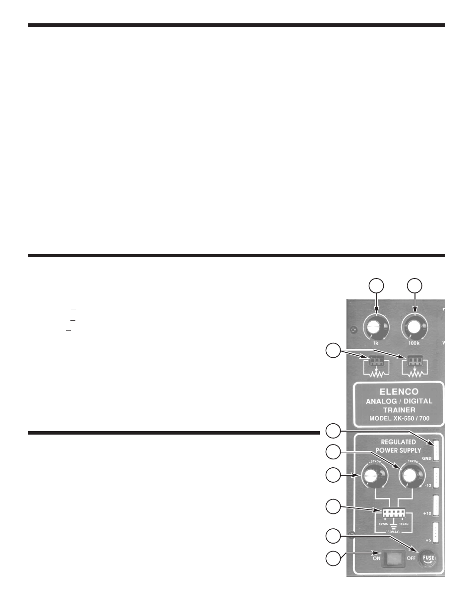
USERS DESCRIPTION OF FRONT PANEL CONTROLS
1) On/Off Switch - Allows power to be applied to all outputs. Switch will
light when on.
2) Fuse Holder - Easy access for replacement of 1.25A fuse.
3) Power Output Terminals - This provides 30VAC center tapped at
15 VAC; also provides output terminal for positive and negative
variable voltages.
4) Variable Positive Voltage Control - Varies positive voltage from 0V
to 20V at indicated output connector pin.
5) Variable Negative Voltage Control - Varies negative voltage from
0V to –20V at indicated output connector pin.
6) Power Output Bredblox - Output terminals for GND, –12, +12, and +5.
7) Output terminals for 1k and 100k undedicated potentiometers.
8) 1k
W
undedicated potentiometer.
9) 100k
W
undedicated potentiometer.
1
2
3
4
5
7
8
9
6