Install components to pc board start here, Continue – Elenco Deluxe Digital / Analog Trainer with Tools Kit Version User Manual
Page 31
-30-
INSTALL COMPONENTS TO PC BOARD
Start Here
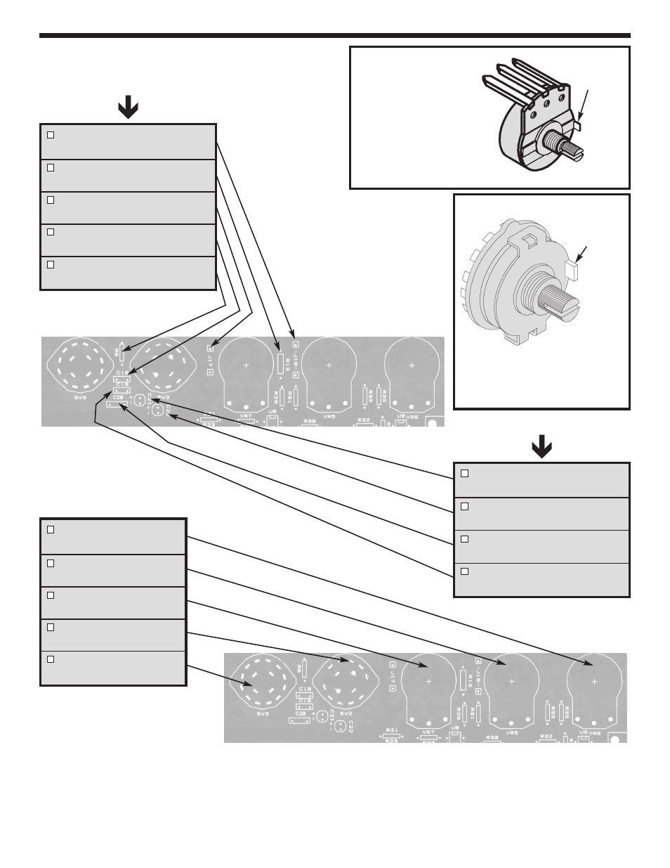
J18 - Jumper Wire
(see Figure A)
R13 - 8.2k
W
5% 1/4W Resistor
(gray-red-red-gold)
J17 - Jumper Wire
(see Figure A)
C18 - .001
m
F (102) Mylar
(see Figure EA)
R6 - 12k
W
5% 1/4W Resistor
(brown-red-orange-gold)
Figure H
Mount down flush with
PC board. The value
may be marked on the
back side of pot.
Cut off excess lead
length after soldering.
Potentiometers
Switches
Figure I
Mount down flush with PC board.
Note: SW2 has 12 pins and SW3
has 16 pins.
VR6 - 100k
W
Pot
(see Figure H)
VR5 - 10k
W
Pot
(see Figure H)
VR7 - 100k
W
Pot
(see Figure H)
SW2 - SW Rotary 12-Pin
(see Figure I)
SW3 - SW Rotary 16-Pin
(see Figure I)
Continue
C21 - 1
m
F 50V Electrolytic
(see Figure D)
C22 - 10
m
F 25V Electrolytic
(see Figure D)
C20 - .1
m
F (104) Mylar
(see Figure EA)
C19 - .01
m
F (103) Mylar
(see Figure EA)
Cut off
tab
Cut off
tab
- SEE AMFM108CK (56 pages)
- Computer Inteface for Snap Circuits® (60 pages)
- Capacitor Substitution Box (8 pages)
- Diode/Transistor Tester Kit (12 pages)
- Diode/Transistor Tester (8 pages)
- Electronic Component Kit (28 pages)
- 100kHz Function Generator in Kit Form (16 pages)
- 100kHz Function Generator (8 pages)
- Surface Mount Generator Kit (16 pages)
- 5MHz Function Generator (12 pages)
- 015V Power Supply Kit (8 pages)
- Resistor Substitution Box (8 pages)
- 3 3/4 Digit Cap./Ind./Logic (2 pages)
- Logic Probe Kit (12 pages)
- Logic Pulser Kit (12 pages)
- Compact Digital Multimeter (20 pages)
- Digital Multimeter (18 pages)
- 3 1/2 Digit Cap. / Trans. Kit (36 pages)
- Compact Multimeter (8 pages)
- Digital Mulitmeter Kit (20 pages)
- 23 Range 20k/V VOM in Kit Form (20 pages)
- 3 1/2 Digit Cap./ Freq./ Trans. w/ Grey Boot (8 pages)
- 3 1/2 Digit with Temperature (36 pages)
- 3 1/2 Digit Cap./ Trans./ Freq (4 pages)
- Digital Bench Multimeter (26 pages)
- MicroMaster ® Computer Training Kit (116 pages)
- 100MHz Scope (68 pages)
- Wide Band RF Generator (7 pages)
- Deluxe Solar Educational Kit (15 pages)
- Soldering Station (20 pages)
- Soldering Station (4 pages)
- Soldering Station (6 pages)
- Surface Mount Technology Kit (12 pages)
- Practical Soldering Project Kit (16 pages)
- DataCom Tester Kit (28 pages)
- MultiModular Cable Tester (4 pages)
- Tone Generator (4 pages)
- Telephone Line Analyzer Kit (16 pages)
- Digital / Analog Trainer Kit Version (52 pages)
- Digital / Analog Trainer in Case (16 pages)
- Digital / Analog Trainer (12 pages)
- Deluxe Digital / Analog Trainer (16 pages)
- Variable Voltage Power Supply Kit (12 pages)
- Variable Voltage Power Supply (8 pages)