Continue install components to pc board start here – Elenco Deluxe Digital / Analog Trainer with Tools Kit Version User Manual
Page 30
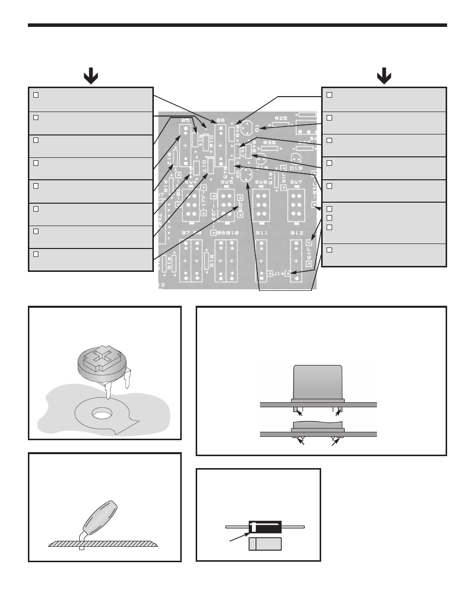
Figure G
Diodes have polarity. Mount with
band in the direction shown on the
PC board.
Figure F
Hold the bredblox down flush to the PC board from the top legend side
and solder the metal pins in place. Then, melt the plastic pins with your
soldering iron to hold the bredblox down as shown. Re-tin the solder tip
afterwards.
Continue
INSTALL COMPONENTS TO PC BOARD
Start Here
B6 - 4-pin Bredblox
(see Figure F)
D16 - 1N4148 Diode
(see Figure G)
R14 - 100
W
5% 1/4W Resistor
(brown-black-brown-gold)
B5 - 4-pin Bredblox
(see Figure F)
R12 - 1k
W
5% 1/4W Resistor
(brown-black-red-gold)
R44 - 100
W
5% 1/4W Resistor
(brown-black-brown-gold)
D17 - 1N4148 Diode
(see Figure G)
J23 - Jumper Wire
(see Figure A)
R48 - 22k
W
5% 1/4W Resistor
(red-red-orange-gold)
Q1 - 2N3904 Transistor
(see Figure C)
R47 - 330
W
5% 1/4W Resistor
(orange-orange-brown-gold)
R46 - 330
W
5% 1/4W Resistor
(orange-orange-brown-gold)
R45 - 22k
W
5% 1/4W Resistor
(red-red-orange-gold)
J16 - Jumper Wire
J15 - Jumper Wire
J14 - Jumper Wire
(see Figure A)
Q2 - 2N3906 Transistor
(see Figure C)
Figure E
Mount the trim pot to the PC board as
shown below.
Figure EA
Bend the capacitors at a 45
o
angle before
soldering it to the PC board.
-29-
Band
Plastic Pins
Melt Pins