Warning, Parts verification, Identifying resistor values – Elenco Deluxe Digital / Analog Trainer with Tools Kit Version User Manual
Page 3: Identifying capacitor values, Ceramic disc mylar, 101k, Axial radial, 2a 22 2j, Resistors capacitors, Connectors switches
-2-
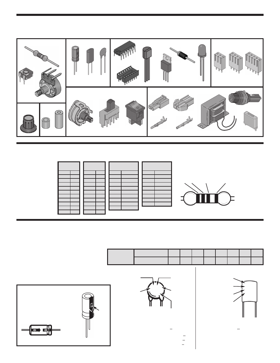
PARTS VERIFICATION
Before beginning the assembly process, first familiarize yourself with the components and this instruction book.
Verify that all parts are present. This is done best by checking off each item in the parts list.
IDENTIFYING RESISTOR VALUES
Use the following information as a guide in properly identifying the value of resistors.
Resistors
Capacitors
Electrolytic
(Lytic)
(Radial)
Connectors
Switches
Mylar
Rotary
DPDT
Discap
Knob
3-Pin
4-Pin
5-Pin
Miscellaneous
Illuminated
Connector plug
Male crimp
terminal
Female crimp
terminal
Integrated circuit (IC)
Transistor
Integrated circuit (IC)
Diode
LED
IDENTIFYING CAPACITOR VALUES
Capacitors will be identified by their capacitance value in pF (picofarads), nF (nanofarads), or
m
F (microfarads). Most
capacitors will have their actual value printed on them. Some capacitors may have their value printed in the following
manner. The maximum operating voltage may also be printed on the capacitor.
PC mount potentiometer
PC mount
trim pot
Semiconductors
IC socket
Bredblox
Connector receptacle
Transformer
Carbon film
Warning:
If the capacitor is
connected with incorrect
polarity, it may heat up and
either leak, or cause the
capacitor to explode.
BANDS
Electrolytic capacitors have a positive and
a negative electrode. The negative lead is
indicated on the packaging by a stripe with
minus signs and possibly arrowheads.
Also, the negative lead of a radial
electrolytic is shorter than the positive one.
Polarity
marking
BAND 1
1st Digit
Color
Digit
Black
0
Brown
1
Red
2
Orange
3
Yellow
4
Green
5
Blue
6
Violet
7
Gray
8
White
9
BAND 2
2nd Digit
Color
Digit
Black
0
Brown
1
Red
2
Orange
3
Yellow
4
Green
5
Blue
6
Violet
7
Gray
8
White
9
Multiplier
Color
Multiplier
Black
1
Brown
10
Red
100
Orange
1,000
Yellow
10,000
Green
100,000
Blue
1,000,000
Silver
0.01
Gold
0.1
Resistance
Tolerance
Color
Tolerance
Silver
±10%
Gold
±5%
Brown
±1%
Red
±2%
Orange
±3%
Green
±0.5%
Blue
±0.25%
Violet
±0.1%
1
2
Multiplier
Tolerance
Multiplier
For the No.
0
1
2
3
4
5
8
9
Multiply By
1
10 100 1k 10k 100k .01 0.1
(+)
(–)
(+)
(–)
Axial
Radial
Second digit
First digit
Multiplier
Tolerance*
Note: The letter “R” may be used at
times to signify a decimal point; as in
3R3 = 3.3
The letter M indicates a tolerance of +20%
The letter K indicates a tolerance of +10%
The letter J indicates a tolerance of +5%
Maximum working voltage
(may or may not appear
on the cap)
The value is 10 x 10 = 100pF, +10%, 50V
*
CERAMIC DISC
MYLAR
First digit
Second digit
Multiplier
Tolerance*
2A
22
2J
10
0V
The value is 22 x 100 =
2,200pF or .0022
m
F, +5%, 100V
101K
50V
Fuse assembly
7/16” x
3/16” tap
Spacers
1/4” #8