Digital troubleshooting chart – Elenco Deluxe Digital / Analog Trainer with Tools Kit Version User Manual
Page 46
TESTING THE LOGIC INDICATOR
FUNCTION
There are eight logic indicators which you will be
checking out. Put a wire to the 5V power supply and
touch the “A” logic indicator test pin. The “A” LED
should light up. Remove the wire and the LED should
go out. Do the same for the B, C, D, E, F, G and H
pins.
TESTING THE LOGIC SWITCHES
There are two logic switches and four conditions to
be checked out. Connect a wire from the “X” test pin
to the “A” logic indicator test pin. Connect another
wire to the “X” test pin to the “B” test pin.
Apply power and note that the “A” LED indicator
should be lit when the logic switch is in the “X”
position and the “B” LED should light and the “A”
LED not light. Check the “Y” logic switch in the same
manner.
TESTING THE DATA SWITCHES
There are eight data switches to be checked. The
output of the switches are 5V or ground depending
on the position. Connect a wire to the SW1 test pin
and the “A” test pin. The “A” LED should light when
the switch is placed toward the top of the case.
Repeat the same test on SW2, SW3, SW4, SW5,
SW6, SW7 and SW8.
r
Unplug the unit from the AC outlet.
-45-
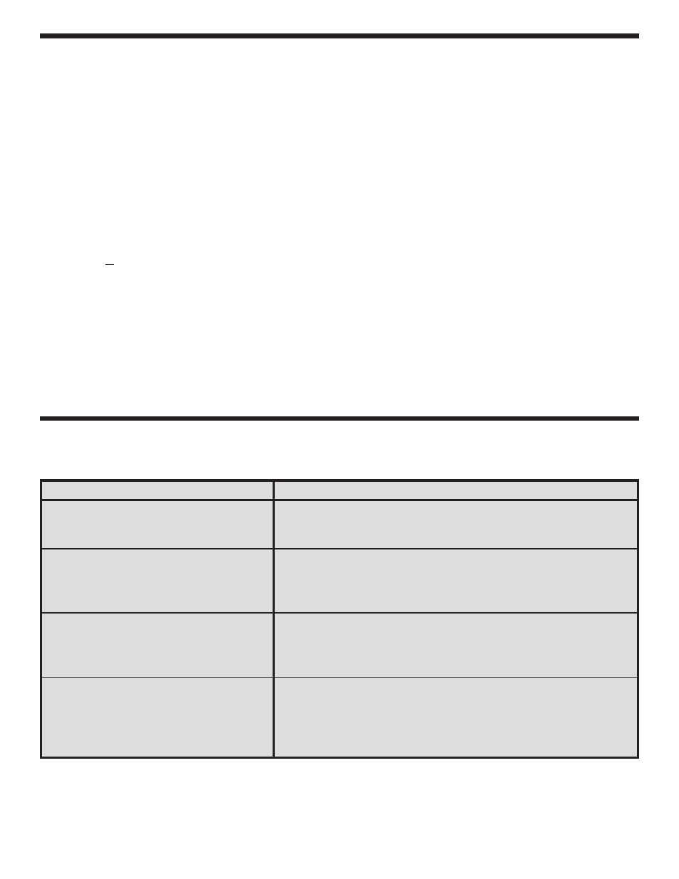
TESTING THE DIGITAL SECTION
PROBLEM
POSSIBLE CAUSE
No +5V on data switch terminals.
1. Measure for a DC voltage of +5V across R15.
A. Check R15, J19, J23 and J13.
B. Switch shorted to ground.
LED doesn’t light
1. Check that the LED is in correctly.
2. Check the input and output resistors.
3. Measure input for +5V and output at ground.
A. Short to ground or defective IC.
LED always on
1. Measure for zero voltage voltage at input pin.
A. Pin shorted or defective IC
2. Measure voltage to output pin for +5V.
A. Pin shorted or defective IC.
Logic switch terminal always high
1. Check that input resistor is grounded.
A. Bad ground connection or switch.
2. Measure for +5V on R16 - R19.
A. Check resistor.
3. Defective IC.
DIGITAL TROUBLESHOOTING CHART