Power supply testing, Troubleshooting chart – Elenco Deluxe Digital / Analog Trainer with Tools Kit Version User Manual
Page 19
-18-
POWER SUPPLY TESTING
PROBLEM
POSSIBLE CAUSE
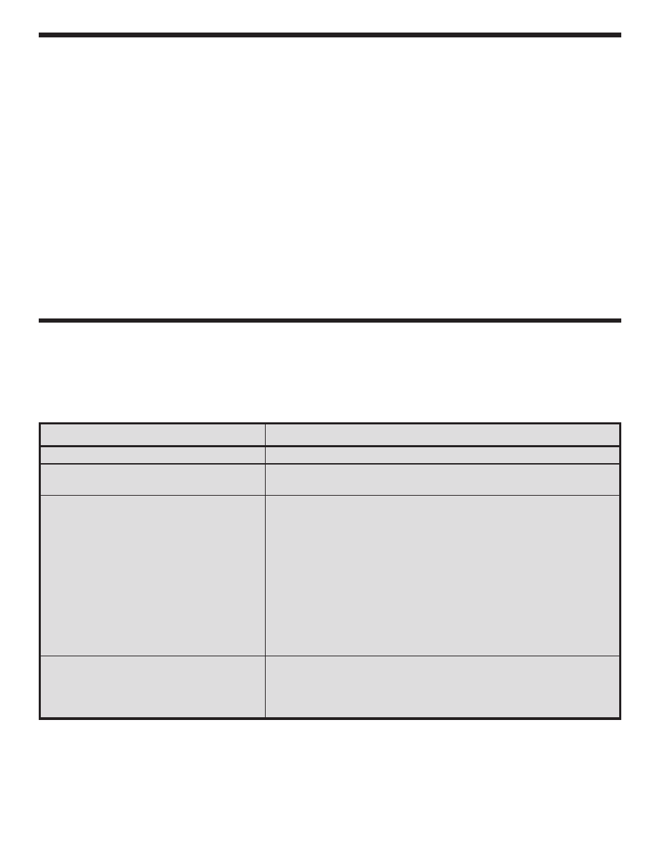
Switch doesn’t light.
1. Check fuse and line cord.
Fuse blows when the unit is turned on.
1. Voltage supply shorted to GND. Use resistance analysis
chart to find short.
No or low voltage at positive variable
1. Measure for an AC voltage of 18VAC at anode of D7 & D9.
output.
A. Transformer and/or secondary connection to PC
board defective
2. Measure for a DC voltage of 28VDC at pin 3 of U1 LM317.
A. Diodes D7, D9 in backwards or defective, check
capacitor C1.
3. Set the voltage for minimum and measure pin 2
of U1.
A. Voltage adjusts only from 7.8 - 9.8V R1 open or
defective.
B. Voltage 27V, check VR1 connections.
No or low voltage at positive variable
1. Check that capacitor C1 1000
m
F is inserted in the correct
output with load.
polarity.
2. Check ripple on pin 3 of U1. 8VP-P Max.
A. Capacitor C1, and/or diodes D7, D9 defective.
Plug the trainer into a 120VAC outlet and switch to
the “ON” position (the power switch should light).
With a digital voltmeter, measure the voltage
outputs at the power blocks. The +12V should
measure between 11.4 and 12.6 volts. The 5V
supply should read between 4.75 and 5.25 volts.
The –12V supply should read between –11.4 and
12.6 volts.
Do not short the 15VAC output to ground.
Short the +12V, –12V and +5V supply to ground.
They should turn off and recover when the short is
removed. If you have a 25
W
10 watt resistor, place
it across the output terminal (2 watt resistor will
work, but use it only for a few seconds). The output
of the 12V supply should not change more than 0.20
volts. Do the same on the 5V supply using a 10
W
5
watt resistor. Again, the output should not change
more than 0.20 volts. In making this test, the
voltmeter leads should be clipped to the terminal
directly and no to the load leads. This is to prevent
errors due to voltage drop from contact resistance
of the load.
Check the variable voltage supplies in the same
manner. Set the output voltage between 10-15
volts. Place the 25
W
10 watt resistor across the
output terminal. The voltage should stay within 0.20
TROUBLESHOOTING CHART
This chart lists the condition and possible causes of several malfunctions. If a particular part is mentioned as a
possible cause, check that part to see if it was installed correctly. Also, check it and the parts connected to it for
good solder connections. Note: The values given in this troubleshooting chart are an approximation.