Install components to pc board, Start here – Elenco Deluxe Digital / Analog Trainer with Tools Kit Version User Manual
Page 7
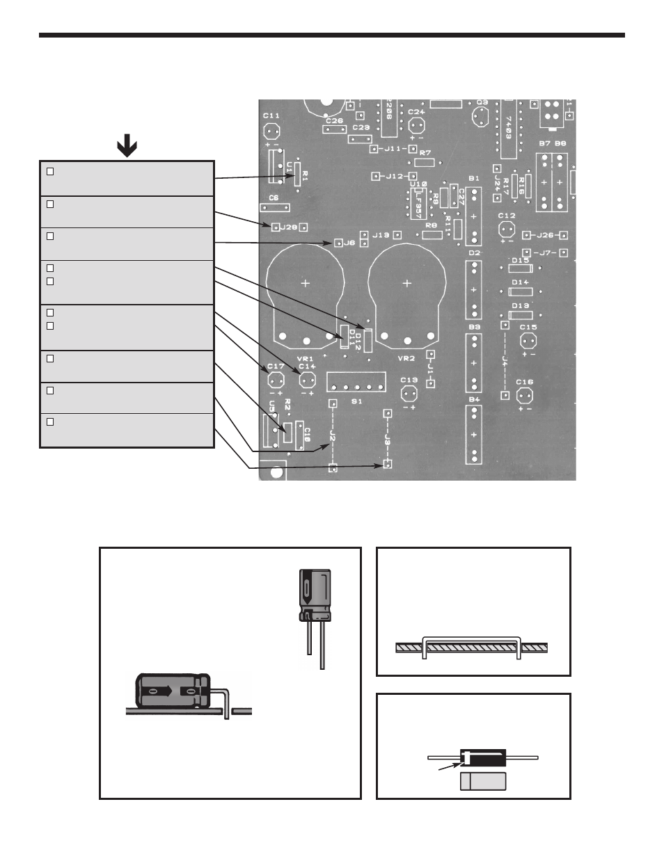
Figure G
Diodes have polarity. Mount them
with the band as shown on the top
legend.
-6-
INSTALL COMPONENTS TO PC BOARD
R1 - 120
W
5% 1/4W resistor
(brown-red-brown-gold)
J28 - Jumper wire
(see Figure F)
J6 - Jumper wire
(see Figure F)
D12 - 1N4001 diode
D11 - 1N4001 diode
(see Figure G)
C14 - 100
m
F 25V lytic
C17 - 100
m
F 25V lytic
(see Figure E)
R2 - 120
W
5% 1/4W resistor
(brown-red-brown-gold)
J2 - Jumper wire
(see Figure F)
J3 - Jumper wire
(see Figure F)
Figure F
Cut a piece of the #22 bare wire
long enough so that 1/4” of wire
passes through each hole in the
PC board after the wire is formed.
Band
Bottom left corner of PC board
Figure E
These capacitors are polarized.
Be sure to mount them with the “+”
lead in the correct hole as marked
on the PC board. Mount the
capacitor lying flat on the PC board
as shown below.
Warning: If the capacitor is connected with
incorrect polarity, it may heat up and either leak
or cause the capacitor to explode.
(+)
(–)
Start Here
- SEE AMFM108CK (56 pages)
- Computer Inteface for Snap Circuits® (60 pages)
- Capacitor Substitution Box (8 pages)
- Diode/Transistor Tester Kit (12 pages)
- Diode/Transistor Tester (8 pages)
- Electronic Component Kit (28 pages)
- 100kHz Function Generator in Kit Form (16 pages)
- 100kHz Function Generator (8 pages)
- Surface Mount Generator Kit (16 pages)
- 5MHz Function Generator (12 pages)
- 015V Power Supply Kit (8 pages)
- Resistor Substitution Box (8 pages)
- 3 3/4 Digit Cap./Ind./Logic (2 pages)
- Logic Probe Kit (12 pages)
- Logic Pulser Kit (12 pages)
- Compact Digital Multimeter (20 pages)
- Digital Multimeter (18 pages)
- 3 1/2 Digit Cap. / Trans. Kit (36 pages)
- Compact Multimeter (8 pages)
- Digital Mulitmeter Kit (20 pages)
- 23 Range 20k/V VOM in Kit Form (20 pages)
- 3 1/2 Digit Cap./ Freq./ Trans. w/ Grey Boot (8 pages)
- 3 1/2 Digit with Temperature (36 pages)
- 3 1/2 Digit Cap./ Trans./ Freq (4 pages)
- Digital Bench Multimeter (26 pages)
- MicroMaster ® Computer Training Kit (116 pages)
- 100MHz Scope (68 pages)
- Wide Band RF Generator (7 pages)
- Deluxe Solar Educational Kit (15 pages)
- Soldering Station (4 pages)
- Soldering Station (6 pages)
- Soldering Station (20 pages)
- Surface Mount Technology Kit (12 pages)
- Practical Soldering Project Kit (16 pages)
- DataCom Tester Kit (28 pages)
- MultiModular Cable Tester (4 pages)
- Tone Generator (4 pages)
- Telephone Line Analyzer Kit (16 pages)
- Digital / Analog Trainer Kit Version (52 pages)
- Digital / Analog Trainer in Case (16 pages)
- Digital / Analog Trainer (12 pages)
- Deluxe Digital / Analog Trainer (16 pages)
- Variable Voltage Power Supply Kit (12 pages)
- Variable Voltage Power Supply (8 pages)