Install components to pc board, Start here – Elenco Deluxe Digital / Analog Trainer with Tools Kit Version User Manual
Page 8
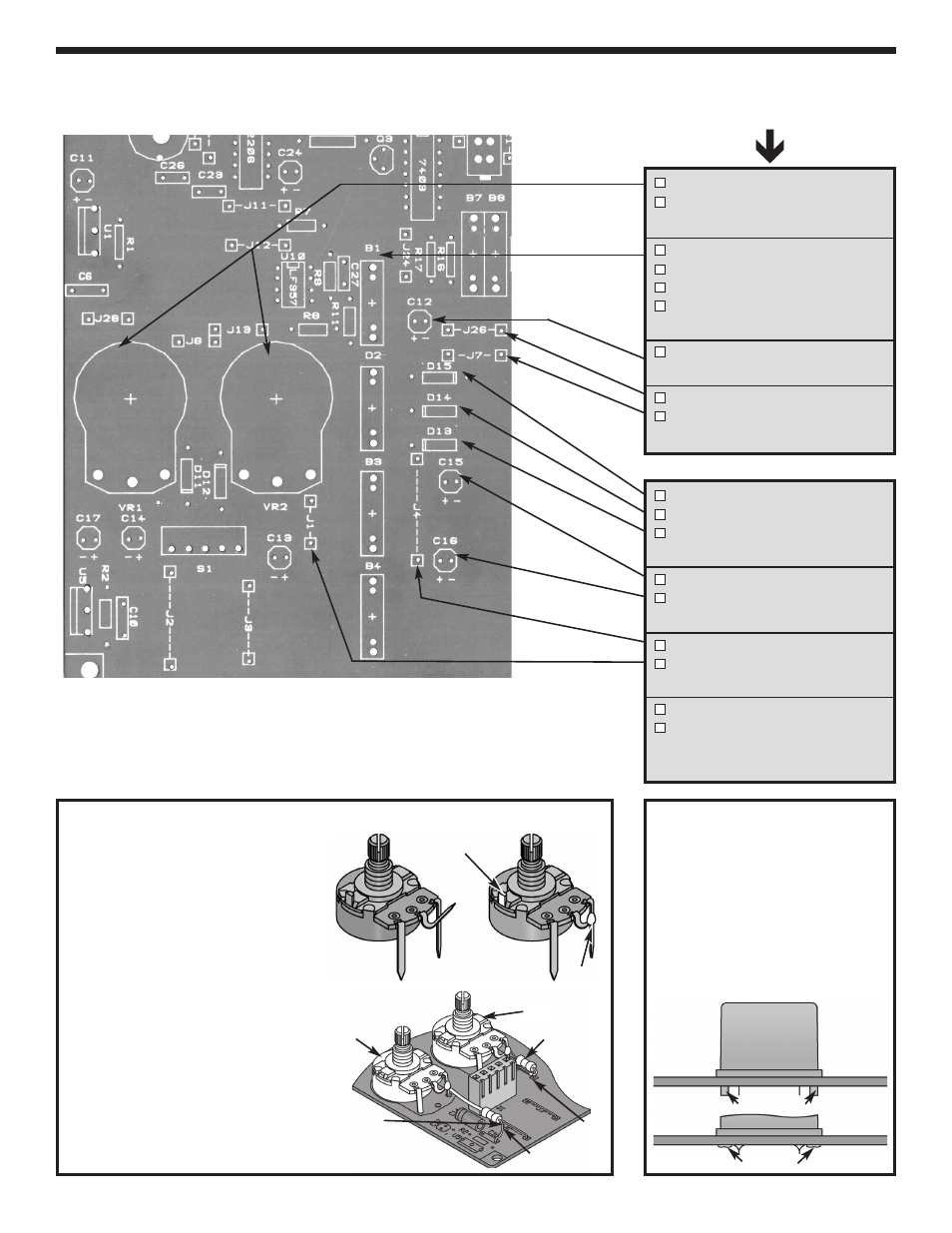
INSTALL COMPONENTS TO PC BOARD
VR1 - 2k
W
pot
VR2 - 2k
W
pot
(see Figure H)
B1 - 4-pin bredblox
B2 - 4-pin bredblox
B3 - 4-pin bredblox
B4 - 4-pin bredblox
(see Figure I)
C12 - 100
m
F 25V lytic
(see Figure E)
J26 - Jumper wire
J7 - Jumper wire
(see Figure F)
D15 - 1N4001 diode
D14 - 1N4001 diode
D13 - 1N4001 diode
(see Figure G)
C15 - 100
m
F 25V lytic
C16 - 100
m
F 25V lytic
(see Figure E)
J4 - Jumper wire
J1 - Jumper wire
(see Figure F)
R50 - 1.2k
W
1/2W resistor
R51 - 1.2k
W
1/2W resistor
(red-red-red-gold)
(see Figure H)
Bottom left corner of PC board
-7-
Figure I
Hold the breadblock down
flush to the PC board from the
top legend side and solder the
metal pins in place. Then, melt
the plastic pins with your
soldering iron to hold the
plastic blocks in place, as
shown.
Start Here
Plastic Pins
Melt Pins
Figure H
1. VR1 and VR2 - Before installing the pot
into the PC board, bend the center lead
over to the right lead and solder. Cut off
the excess leads.
2. Install the pots flush with the PC
board. The value may be marked on
the back of the pot. Cut off the excess
lead length after soldering.
3. Place the 3/4” tubing over one lead of
the 1.2k
W
5% 1/2W (red-red-red-gold)
resistor. Postion the resistor as shown.
Solder the resistor from the bottom
hole of C10 to the right lead of VR1 as
shown.
Solder a 1.2k
W
5% 1/2W (red-red-red-
gold) resistor from jumper J1 to the
right lead of VR2 as shown.
Caution:
Make sure
resistor lead does not
short to jumper wire.
VR1
VR2
Cut off tab
R50
R51
J1
Solder