Wire switch and fuse holder (see figure z) – Elenco Deluxe Digital / Analog Trainer with Tools Kit Version User Manual
Page 15
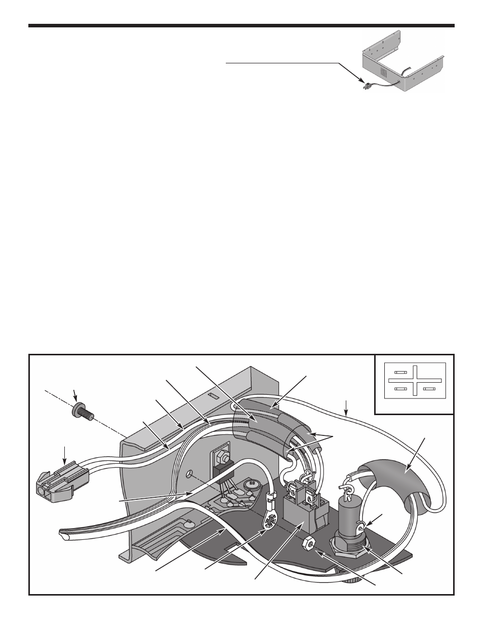
WIRE SWITCH AND FUSE HOLDER (see Figure Z)
Line Cord
r
Slide the line cord through the frame as shown.
r
Spread the three line cord wires apart 6” from the end.
r
Mount the solder lug to the side panel using a 6-32 x 5/16” screw and 6-32 nut.
Fuse
r
Strip the insulation off of both ends of the 6” red wire to expose 1/4” of bare wire. Pass the wire through the
1/2” diameter shrink tubing. Attach one end to the side lug on the fuse holder and then solder into place.
r
Pass the smooth edged line cord wire through the 1/2” diameter shrink tubing and attach to the end lug on
the fuse holder, solder into place.
r
Slide the shrink tubing over the fuse holder covering both lugs. Shrink the tubing for a snug fit. You may use
a hair dryer, heat gun (at lowest setting or you will melt the tubing) or the heat emitting from your soldering
iron (do not touch the tubing or the wires with the iron).
Switch
Disconnect the connector for the transformer.
r
Pass the 6” strip of red wire (leading from the side lug of the fuse holder), the (A) and (B) black transformer
wire, and the ribbed line cord wire through the 3/4” diameter piece of shrink tubing.
r
Cut the 2” section of 3/16” diameter shrink tubing in half to create two 1” sections. Slide a 3/16” diameter
piece of shrink tubing over the loose end of the red wire. Attach the red wire to lug 1 on the switch and
then solder into place.
r
Pass the black transformer wire labeled (B) through a 3/16” diameter piece of shrink tubing. Attach the wire
to lug 2 on the switch and then solder into place.
r
Slide the shrink tubing over lug 1 and lug 2 on the switch. Shrink the tubing into place.
r
Strip the insulation off of the black transformer wire (A) and the ribbed edged line cord wire to expose 1/2” of
bare wire. Twist the two bare wires together. Pass the wires through the 1/4” diameter piece of shrink tubing.
Attach the wires to lug 3 on the switch and solder into place. Slide the tubing over the lug. Shrink the tubing
into place.
r
Slide the 3/4” diameter shrink tubing over the switch and shrink into place.
r
Reconnect the connector for the transformer.
-14-
Fuse holder
6-32 Nut
Side lug
6” Red wire
1/2” Dia.
shrink tubing
3/16” Dia.
shrink tubing
(B) Black
transformer wire
Female connector
Smooth line
cord wire
Ribbed line cord wire
Green line
cord wire
Solder lug
3/4” Dia. shrink tubing
1/4” Dia. shrink tubing
Switch
Figure Z
Switch Pin-out
1
2
3
(A) Black
transformer wire
6-32 x 5/16”
Screw