Continue install components to pc board start here, Continue – Elenco Deluxe Digital / Analog Trainer with Tools Kit Version User Manual
Page 42
-41-
Continue
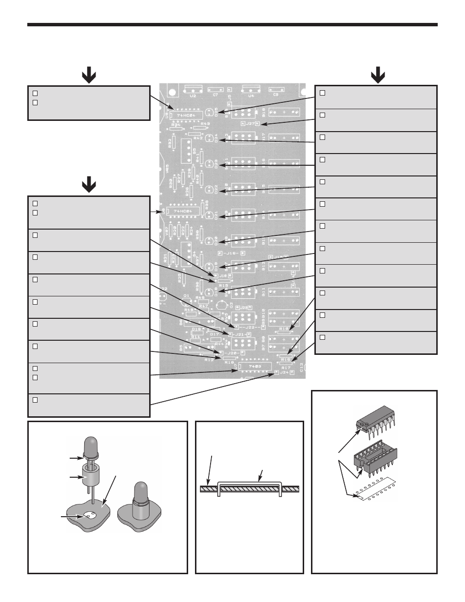
INSTALL COMPONENTS TO PC BOARD
Start Here
U9 - IC socket 14-pin
U9 - 74HC04 IC
(see Figure D)
Continue
D25 - LED and Spacer
(see Figure B)
J27 - Jumper Wire
(see Figure C)
D24 - LED and Spacer
(see Figure B)
D23 - LED and Spacer
(see Figure B)
D22 - LED and Spacer
(see Figure B)
D21 - LED and Spacer
(see Figure B)
D20 - LED and Spacer
(see Figure B)
D19 - LED and Spacer
(see Figure B)
D18 - LED and Spacer
(see Figure B)
R19 - 1k
W
5% 1/4W Resistor
(brown-black-red-gold)
R16 - 1k
W
5% 1/4W Resistor
(brown-black-red-gold)
R17 - 1k
W
5% 1/4W Resistor
(brown-black-red-gold)
U8 - 14-pin IC socket
U8 - 74HC04 IC
(see Figure D)
J19 - Jumper Wire
(see Figure C)
R15 - 220
W
5% 1/4W Resistor
(red-red-brown-gold)
J22 - Jumper Wire
(see Figure C)
J21 - Jumper Wire
(see Figure C)
J20 - Jumper Wire
(see Figure C)
R18 - 1k
W
5% 1/4W Resistor
(brown-black-red-gold)
U7 - IC socket 14-pin
U7 - 7403 IC
(see Figure D)
J24 - Jumper Wire
(see Figure C)
Figure C
Cut a piece of bare wire long
enough so that 1/4” of wire
passes through each hole in
the PC board after the wire is
formed (provided in the
second package).
Figure B
Mount spacer and LED flush to the PC board,
with the flat side of the LED in the same
direction as the marking on the top legend
side of the PC board.
Flat
Spacer
Figure D
Insert the IC socket into the PC
board with the notch in the
direction shown on the top legend.
Solder the IC socket into place.
Insert the IC into the socket with
the notch in the same direction as
the notch on the socket.
IC socket
IC
Notch
Top legend side of PC board
Flat
Top legend side of PC board
Jumper wire