Continue install components to pc board start here – Elenco Deluxe Digital / Analog Trainer with Tools Kit Version User Manual
Page 29
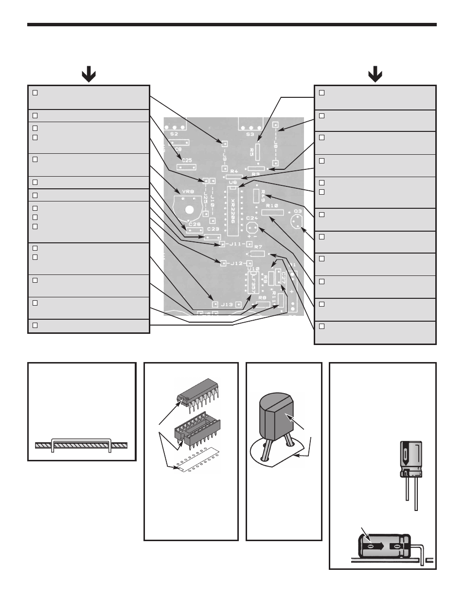
Figure B
Insert the IC socket into the PC
board with the notch in the
direction shown on the top
legend. Solder the IC socket
into place. Insert the IC into the
socket with the notch in the
same direction as the notch on
the socket.
Figure C
Mount the transistor
with the flat side in
the direction shown
on the top legend.
Continue
INSTALL COMPONENTS TO PC BOARD
Start Here
J9 - Jumper Wire
(see Figure A)
C25 - .0022
m
F (222) Discap
J10 - Jumper Wire
J25 - Jumper Wire
(see Figure A)
VR8 - 100k
W
Trim Pot
(see Figure E)
C26 - 22pF (22) Discap
C23 - 100pF (101) Discap
J11 - Jumper Wire
J12 - Jumper Wire
J13 - Jumper Wire
(see Figure A)
U10 - IC socket 8-pin
U10 - LM318 IC
(see Figure B)
R8 - 51k
W
5% 1/4W Resistor
(green-brown-orange-gold)
R11 - 4.7k
W
5% 1/4W Resistor
(yellow-violet-red-gold)
C27 - 5pF (5) Discap
R5 - 200
W
5% 1/4W Resistor
(red-black-brown-gold)
J8 - Jumper Wire
(see Figure A)
R3 - 6.8k
W
5% 1/4W Resistor
(blue-gray-red-gold)
R4 - 22k
W
5% 1/4W Resistor
(red-red-orange-gold)
U6 - IC socket 16-pin
U6 - XR2206 IC
(see Figure B)
R49 - 2k
W
5% 1/4W Resistor
(red-black-red-gold)
Q3 - 2N3904 Transistor
(see Figure C)
R10 - 10k
W
5% 1/4W Resistor
(brown-black-orange-gold)
C24 - 10
m
F 25V Lytic
(see Figure D)
R7 - 4.7k
W
5% 1/4W Resistor
(yellow-violet-red-gold)
R9 - 47k
W
5% 1/4W Resistor
(yellow-violet-orange-gold)
Figure A
Cut a piece of bare wire long
enough so that 1/4” of wire
passes through each hole in
the PC board after the wire is
formed (provided in the
second package).
Socket
IC
Notch
-28-
Figure D
Electrolytics have a polarity
marking on them indicating
the negative (–) lead. The
PC board is marked to show
the lead positions.
Mount the capacitors hori-
zontal to the PC
board.
Bend the leads
at right angles
and then insert
the leads into
the PC board.
Flat
(+)
(–)
Polarity mark