Display Devices Lifts up up 35 lbs User Manual
Page 14
IP025-001 V3
IBL Lift Series Installation
07/05
Thor/Sales Info/Installation Materials/IBL Lift
14
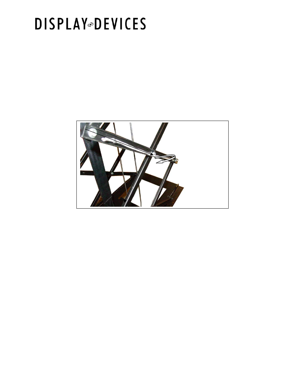
Attaching the Cables
1.)
Using the hand-held remote, lower the lift down to the MAINTENANCE position.
See the enclosed remote control instructions for information about how to
program this position. The signal, power, and control cables can now be routed
into the cable management clips on sides of the scissor assembly.
2.)
The lift is shipped with a sample cable in the clips. Attach your cables in a
likewise manner. Small cable tie wraps are supplied for securing the cables into
the clips.
3.)
Carefully route the projector cables starting at the bottom scissor towards the
front of the lift and work towards the top front of the lift. Please note that the
cables alternate inside-to-outside on the scissors. Be careful to avoid
twisting the cable.
NOTE:
It is common practice to keep the signal cables (audio, video, RGB) separate from the
projector power and control cables to prevent signal interference. Utilize the clips on
both sides of the lift for isolation.
4.)
Raise the lift to its home position with the UP button (in MANUAL mode) slowly,
carefully, and intermittently. Carefully observe the cables rigged to the sides of
the lift and watch for any problems.
5.) Lower
the
lift down with the DOWN button again watching for any problems and
ensuring proper overall operation. Repeat this process several times.
6.)
If you did not set the 12-volt trigger and AC configuration, revisit Part 1 and set
the Dip Switches for your system design. You are now ready to attach the
ceiling panel closure.