3 > installation diagram – Austin Hughes IGM-03 User Manual
Page 8
www.austin-hughes.com
UM-IGM-03-Q314V1
P.3
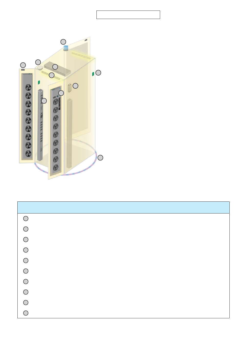
Item
Qty.
Location
EC Box
1
rackmount on rear top
LED Light Bar
2
front & rear top inside
Smoke Sensor
1
rear inside top
Door Sensor
2
top corner of door
Flashing LED Beacon
1
front cabinet roof
Temp. & Humid. Sensor
2
any inside position
Shock Sensor
1
upper inside
Fan Unit
4
door mount or rackmount
PDU
4
vertical or rackmount
Water Sensor
1
surrounding cabinet on floor
< 1.3 > Installation Diagram
1
3
6
10
2
4
8
7
5
9
1
3
6
9
2
4
8
7
10
5
One Box One Cabinet
Front Door