Oops! jumper (bios recovery) serial console, Serial console bios setup hot (serial) cable, Figure 3-2 – ADLINK CoreModule 435 User Manual
Page 40: Oops! jumper, Figure 3-3, Hot cable jumper, Oops! jumper (bios recovery), Serial console
Chapter 3
Hardware
34
Reference Manual
CoreModule 435
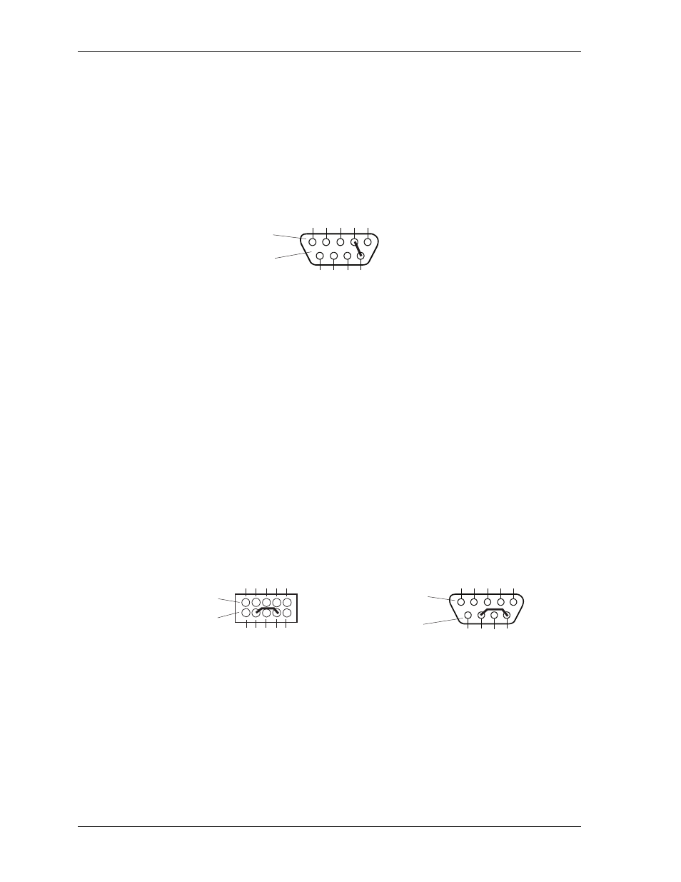
Oops! Jumper (BIOS Recovery)
The Oops! jumper is provided in the event you have selected BIOS settings that prevent you from booting
the system. By using the Oops! Jumper you can stop the current BIOS settings in the CMOS from being
loaded, allowing you to proceed, using the default settings. Connect the DTR pin to the RI pin on Serial port
1 (COM 1) prior to boot up to prevent the present BIOS settings from loading. After booting with the Oops!
Jumper in place, remove the Oops! Jumper and go into the BIOS Setup Utility. Change the desired BIOS
settings, or select the default settings, and save changes before rebooting the system.
To convert a standard DB9 connector to an Oops! Jumper, short together the DTR (4) and RI (9) pins on the
rear of the connector as shown in
on the Serial Port 1 DB9 connector.
Figure 3-2. Oops! Jumper
Serial Console
The CoreModule 435 BIOS supports the serial console (or console redirection) feature. These I/O functions
are provided by an ANSI-compatible serial terminal, or the equivalent terminal emulation software running
on another system. This can be very useful when setting up the BIOS on a production line for systems that
are not connected to a keyboard and display.
Serial Console BIOS Setup
The serial console (console redirection) feature is implemented by connecting a standard null-modem cable
or a modified serial cable (or “Hot Cable”) from either serial port COM1 or COM2 (J3 or J9) to the serial
terminal or a PC with communications software. The BIOS Setup Utility controls the serial console settings
on the CoreModule 435. Refer to the BIOS Setup for the serial console option settings using a serial terminal
or PC with communications software.
Hot (Serial) Cable
To convert a standard serial cable to a Hot Cable, certain pins must be shorted together at the Serial port
header or at the DB9 connector. Short together the RTS (4) and RI (8) pins on either the COM1 or COM2
(J3 or J9) header. As an alternate, you can short the equivalent pins (pins 7 and 9) on the back of the
respective DB9 connector as shown in
Figure 3-3. Hot Cable Jumper
CM435_Oopsjump
Standard DB9 Serial
Port Connector (Female)
Rear View
5
4
3
2
1
9
8
7
6
CM435_HotCable
5
4
3
2
1
9
8
7
6
Standard DB9 Serial
Port Connector (Female)
Rear View
(or Front View of
Male Connector)
Or
1
3
5
7
9
2
4
6
8
10
Serial Port Header
(COM1 or COM2)