Miscellaneous, Real time clock (rtc) user gpio interface, Table 3-16 – ADLINK CoreModule 435 User Manual
Page 39: User gpio interface pin signals (j8)
Chapter 3
Hardware
CoreModule 435
Reference Manual
33
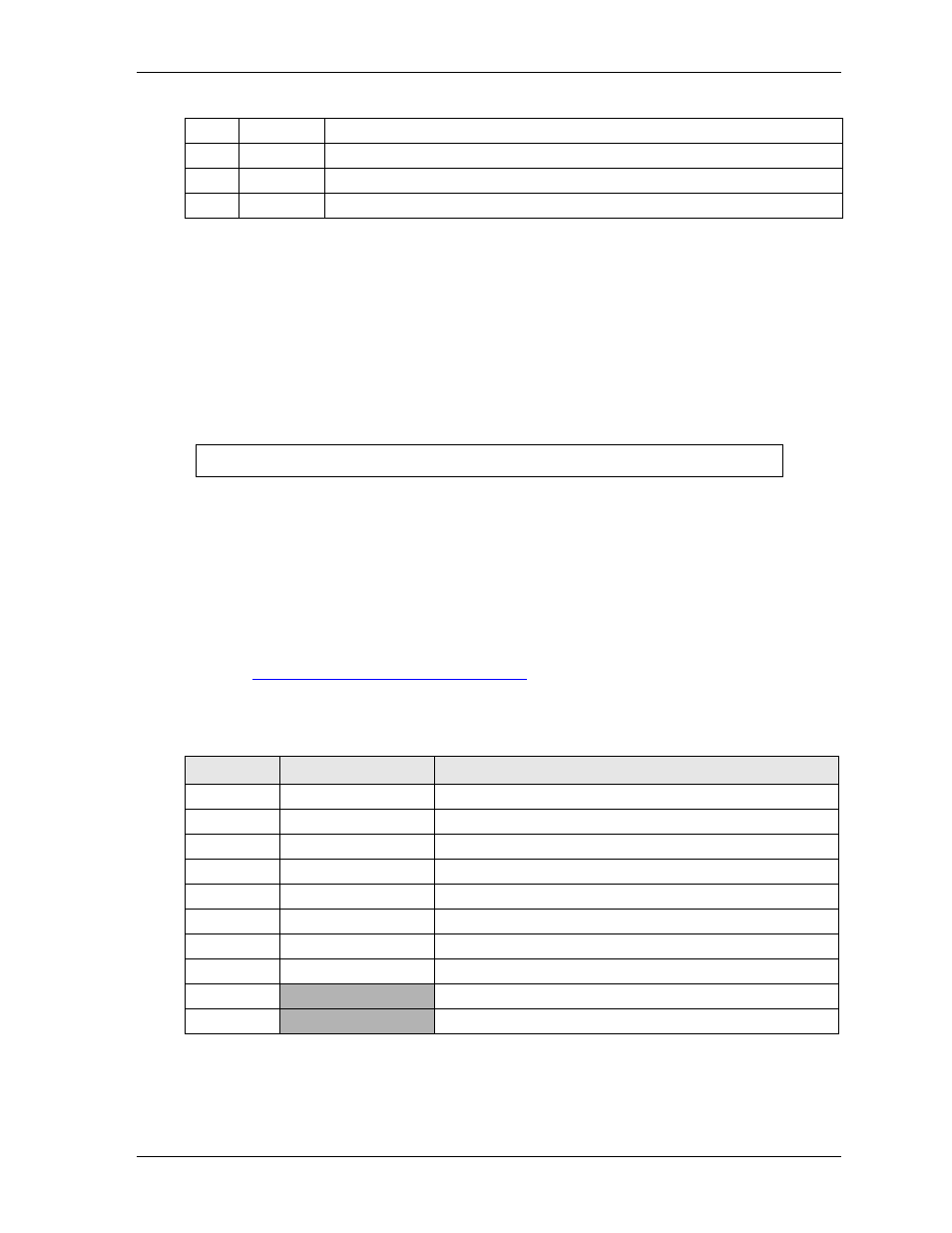
Note: The shaded table cells denote power or ground.
Miscellaneous
Real Time Clock (RTC)
The CoreModule 435 contains a Real Time (time of day) Clock (RTC), which can be backed up with an
external Lithium Battery. The CoreModule 435 will function without a battery in those environments which
prohibit batteries. The CoreModule 435 will also continue to operate after the battery life has been
exceeded. Under these conditions all setup information is restored from the on-board flash memory during
POST along with the default date and time information.
User GPIO Interface
The CoreModule 435 provides GPIO pins for customer use, and the signals are routed to header J8. An
example of how to use the GPIO pins resides in the Miscellaneous Source Code Examples on the
CoreModule 435 Support Software QuickDrive.
The example program can be built by using the make.bat file. This produces a 16-bit DOS executable
application, gpio.exe, which can be run on the CoreModule 435 to demonstrate the use of GPIO pins. For
more information about the GPIO pin operation, refer to the Programming Manual for the Vortex processor
at:
http://www.vortex86sx.com/?page_id=3.pdf
describes the pin signals of the GPIO interface, which uses a 10-pin header with 2 rows, odd/
even sequence (1, 2), and 0.079" (2mm) pitch.
Note: The shaded table cells denote ground.
7
CLK_PCI
PCI Clock
8
AD1
Command, Address, and Data 1
9
FRAME
Frame Signals - indicate start of new cycle or termination of broken cycle
10
AD0
Command, Address, and Data 0
NOTE
Some operating systems require a valid default date and time to function.
Table 3-16. User GPIO Interface Pin Signals (J8)
Pin #
Signal
Description
1
GPIO0
User defined
2
GPIO1
User defined
3
GPIO2
User defined
4
GPIO3
User defined
5
GPIO4
User defined
6
GPIO5
User defined
7
GPIO6
User defined
8
GPIO7
User defined
9
GND
Ground
10
GND
Ground
Table 3-15. LPC Interface Pin Signals (J20) (Continued)