Header, connector, and socket definitions, Figure 2-4, Component locations (bottom side) – ADLINK CoreModule 435 User Manual
Page 16: Table 2-2, Header, connector, and socket descriptions, T1 u2, U4 u9
Chapter 2
Product Overview
10
Reference Manual
CoreModule 435
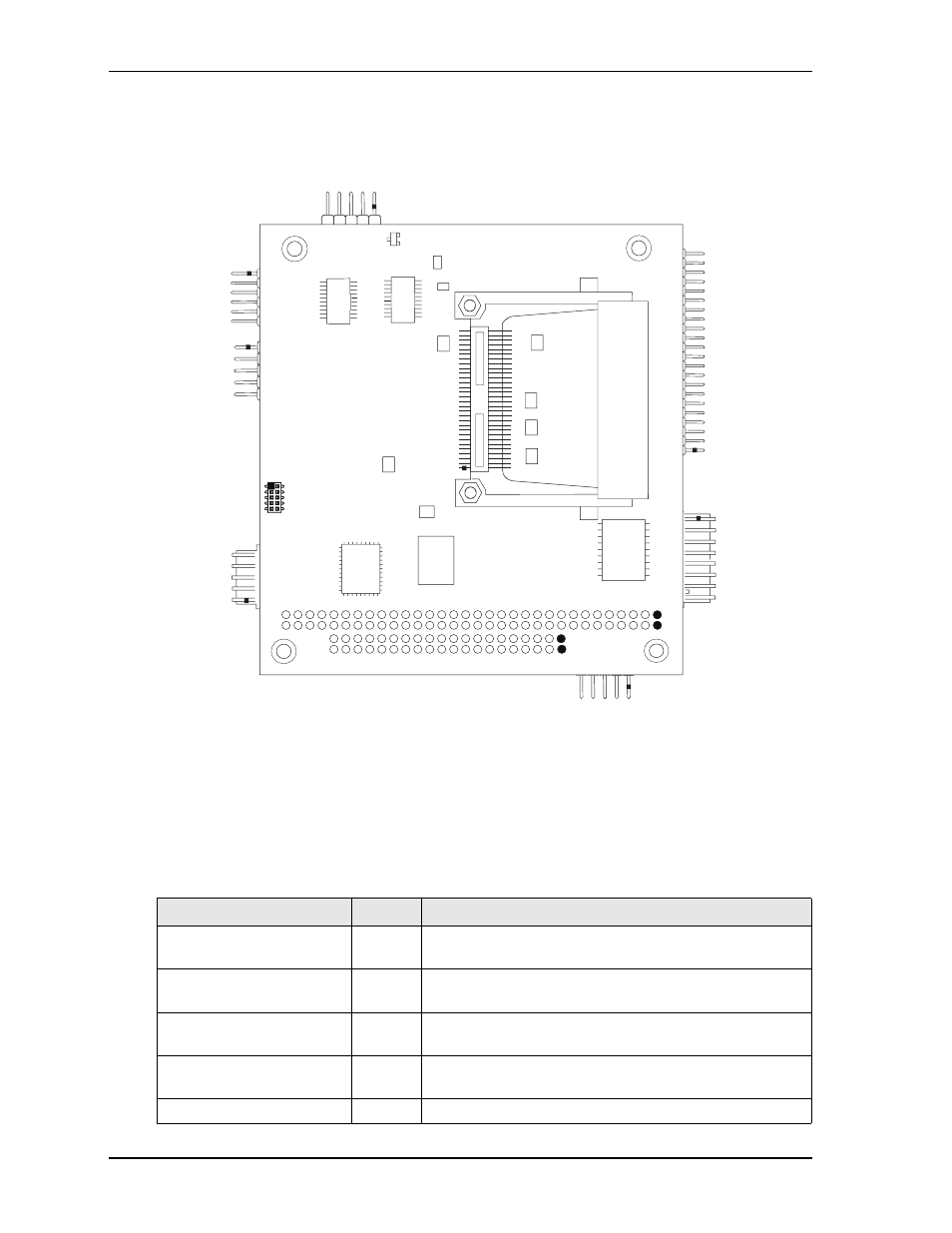
Figure 2-4. Component Locations (Bottom Side)
Header, Connector, and Socket Definitions
describes the headers, connector, and socket shown in
.
Table 2-2. Header, Connector, and Socket Descriptions
Jack/Plug #
Access
Description
P1 – PC/104 Bus
Top/
Bottom
104-pin, 0.100" (2.54mm) connector for standard PC/104
(ISA) bus
J2 – Fast Ethernet
Top
8-pin, 0.100" (2.54mm), right-angle header for
(10baseT/100baseTX) Fast Ethernet interface
J3 – Serial 1 (COM1)
Top
10-pin, 0.100" (2.54mm), right-angle header for Serial 1
interface
J5 – Utility
Top
10-pin, 0.100" (2.54mm), right-angle header for Utility
interface
J6 – IDE
Top
44-pin, 0.079" (2mm) header for standard IDE interface
CM435_comp_bottom_a
T1
U2
Key:
U2
- DDR2 SDRAM - System Memory
U4
- RS-232 Transceiver - COM3
U9
- RS-422/485 Transceiver - COM1 and COM2
T1
- 10/100/1000 Ethernet Transformer
U4
U9