Utility interface, Keyboard mouse battery reset switch speaker, Table 3-9 – ADLINK CoreModule 435 User Manual
Page 33: Utility interface pin signals (j5)
Chapter 3
Hardware
CoreModule 435
Reference Manual
27
Utility Interface
The Utility interface provides various utility and I/O signals on the module and consists of a 10-pin, 0.1"
(2.54mm) pitch header. The Vortex CPU drives the signals on the Utility interface, and
provides
the signal definitions.
•
PS/2 Keyboard and PS/2 Mouse
•
Battery
•
Reset Switch
•
Speaker
Keyboard
The signal lines for a PS/2 keyboard are provided from the Vortex CPU to the Utility interface.
Mouse
The signal lines for a PS/2 mouse are provided from the Vortex CPU to the Utility interface.
Battery
An external battery input connection is provided through the Utility interface to support a battery backup for
the CMOS RAM and the RTC (Real Time Clock).
Reset Switch
An external reset switch provides the reset signal through the Utility interface to a reset circuit, which drives
the Vortex CPU.
Speaker
The speaker signal provides sufficient signal strength to drive a 1W 8
Ω
“Beep” speaker through the Utility
interface at an audible level. The speaker signal is driven from an on-board amplifier and the Vortex CPU.
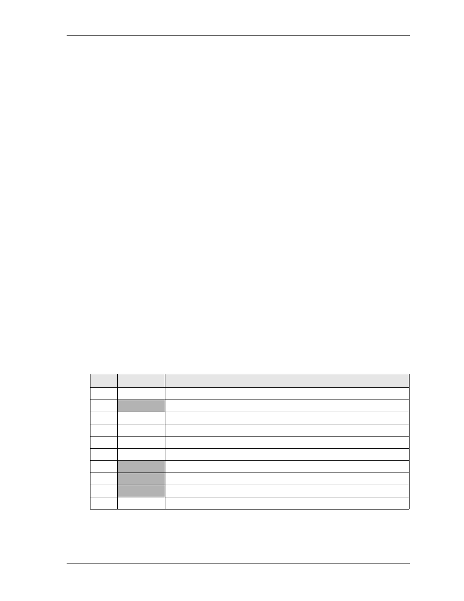
describes the pin signals of the Utility interface, which uses a 10-pin, right-angle header with 2
rows, odd/even sequence (1, 2), and 0.100" (2.54mm) pitch.
Note: The shaded table cells denote power or ground. The * symbol indicates the signal is Active Low.
Table 3-9. Utility Interface Pin Signals (J5)
Pin #
Signal
Description
1
SPKR
Speaker Output
2
BATV-
Ground return
3
RESETSW*
External Reset Switch signal
4
MDATA
Mouse Data input
5
KBDATA
Keyboard Data input
6
KBCLK
Keyboard Clock input
7
GND
Ground
8
KMPWR
Keyboard /Mouse power (+5V) output
9
BATV+
Real time battery voltage (3.6V Type/ 4.0V Max) input
10
MCLK
Mouse Clock input