Figure 2-3, Component locations (top side), Figures 2-3 – ADLINK CoreModule 435 User Manual
Page 15
Chapter 2
Product Overview
CoreModule 435
Reference Manual
9
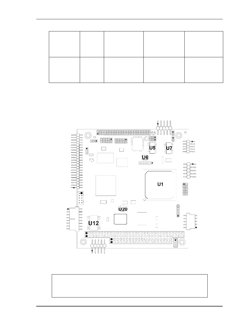
Figure 2-3. Component Locations (Top Side)
Ethernet
EEPROM
(U20)
Atmel
AT93C46DN-SH
Three-Wire Serial
EEPROM for Gigabit
Ethernet Controller
Provides storage for
MAC addresses,
serial numbers, and
pre-boot
configuration data
Ethernet
Transformer
(T1 - on bottom
side) [see
Wurth
Elektronik
7490200110
Gigabit Ethernet
Magnetics
Provides electrical
isolation for Gigabit
Ethernet controller
NOTE
Black dots on vertical headers or connectors indicate pin 1 in all illustrations.
Black dots on right-angle headers or connectors indicate pin 1 in top-side views
and pin 2 in bottom-side views (except for on the J7 Power header, which
indicates pin 2 in top-side views and pin 1 in bottom-side views.)
Table 2-1. Major Component (IC) Descriptions and Functions (Continued)
CM435_comp_top_a
Key:
U1
- CPU
U3
- DDR2 SDRAM - System Memory
U5
- RS-232 Transceiver - COM4
U6
- SPI Flash - Data Storage
U7
- RS-232 Transceiver - COM1 and COM2
U12 - 10/100 Ethernet Transformer
U13 - PCI Graphics Controller
U14 - DDR2 SDRAM - Video Memory
U19 - 10/100/1000 Ethernet Controller
U20 - 10/100/1000 Ethernet EEPROM
U12
U19
U20
U3
U14
U13
U1
U7
U5
U6