Usb interface, Table 3-7, Usb0 interface pin signals (j10) – ADLINK CoreModule 435 User Manual
Page 32: Table 3-8, Usb1 interface pin signals (j17)
Chapter 3
Hardware
26
Reference Manual
CoreModule 435
USB Interface
The CoreModule 435 contains one root USB (Universal Serial Bus) hub and two functional USB ports. The
Vortex CPU provides the USB function including the following features:
•
Provides one root hub with two USB ports
•
Supports USB EHCI v.2.0 and USB OHCI v.1.1
•
Provides over-current detection status
•
Provides a fuse (F1, 1.5A) on board for over-current protection
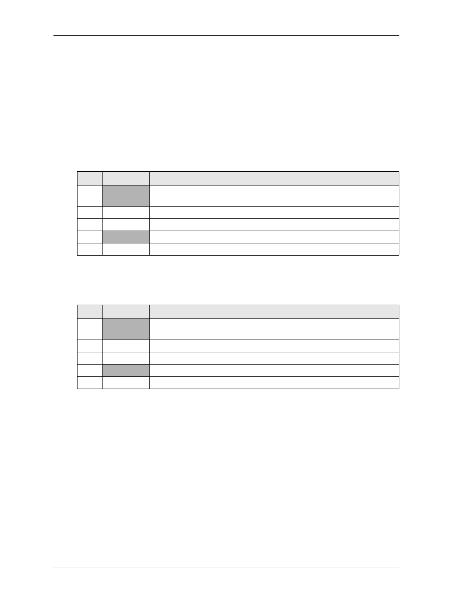
describes the pin signals of the USB0 interface, which uses a single-row, 5-pin, right-angle header
with 0.100" (2.54mm) pitch.
Note: The shaded table cells denote power or ground.
describes the pin signals of the USB1 interface, which uses a single-row, 5-pin, vertical header
with 0.079" (2mm) pitch.
Note: The shaded table cells denote power or ground.
Table 3-7. USB0 Interface Pin Signals (J10)
Pin #
Signal
Description
1
USB0PWR
USB Power – VCC (+5V +/-5%) power goes to the port through an on-board
fuse. Port is disabled if this input is low.
2
USB0N
USB0 Port Data Negative
3
USB0P
USB0 Port Data Positive
4
GND
USB0 Port ground
5
SHIELD
USB0 Port shield
Table 3-8. USB1 Interface Pin Signals (J17)
Pin #
Signal
Description
1
USB1PWR
USB Power – VCC (+5V +/-5%) power goes to the port through an on-board
fuse. Port is disabled if this input is low.
2
USB1N
USB1 Port Data Negative.
3
USB1P
USB1 Port Data Positive
4
GND
USB1 Port ground
5
SHIELD
USB1 Port shield