Figure 3-1, Rs-485 serial port implementation, Table 3-5 – ADLINK CoreModule 435 User Manual
Page 30
Chapter 3
Hardware
24
Reference Manual
CoreModule 435
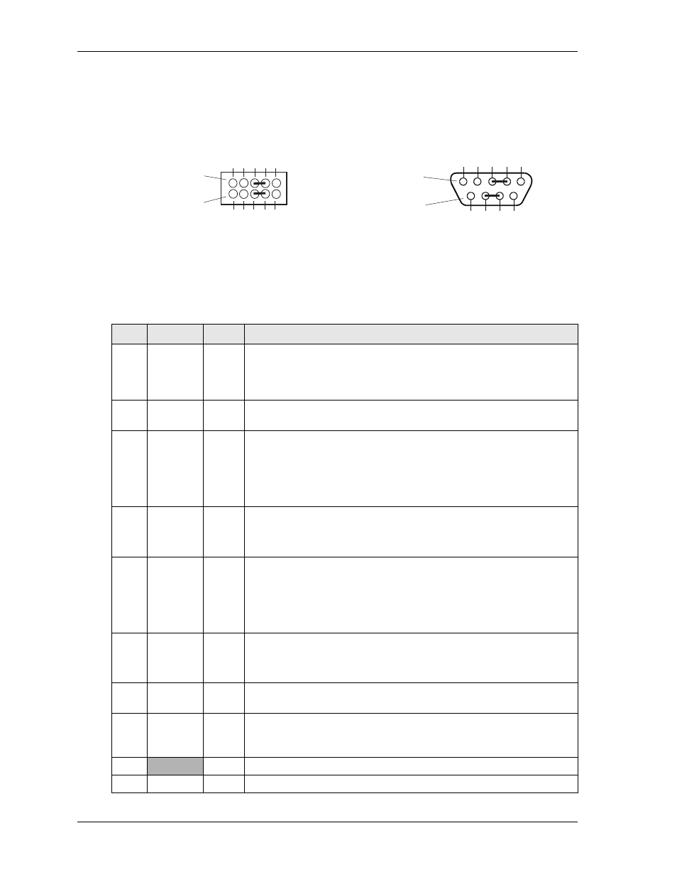
For example, you must tie pin 3 (Rx Data –) to pin 5 (Tx Data –) and pin 4 (Tx Data +) to pin 6 (Rx Data +)
at Serial Port 1 or 2 (J3 or J9) for the two-wire interface. As an alternate, you may short the equivalent pins
on the DB9 connector attached to respective serial port, as shown in
. Refer also to the following
tables for the specific pins on the connectors. The RS-422 mode uses a four-wire interface and does not
require combining pins for its operation, but you must select RS-485 in BIOS Setup.
Figure 3-1. RS-485 Serial Port Implementation
provides the signals for the corresponding pins of the two independent serial interfaces: Serial 1 &
2.
provides the signals for the corresponding pins of the two independent serial interfaces: Serial 3
& 4. Both interfaces use 10-pin, right-angle headers with 2 rows, odd/even sequence (1, 2), and 0.100"
(2.54mm) pitch.
Note: The shaded table cells denote power or ground. The * symbol indicates the signal is Active Low.
Table 3-5. Serial Port 1 (J3) & Port 2 (J9) Interface Pin Signals
Pin # Signal
DB9 # Description
1
DCD*
1
Data Carrier Detect – Indicates external serial device is detecting a
carrier signal (i.e., a communication channel is currently open). In direct
connect environments, this input is driven by DTR as part of the DTR/
DSR handshake.
2
DSR*
6
Data Set Ready – Indicates external serial device is powered, initialized,
and ready. Used as hardware handshake with DTR for overall readiness.
3
RXD
Rx Data –
2
Receive Data – Serial port receive data input is typically held at a logic 1
(mark) when no data is being transmitted, and is held “Off” for a brief
interval after an “On” to “Off” transition on the RTS line to allow the
transmission to complete.
Serial Port 1 or 2 – If in RS-485 mode, this pin is Rx Data Negative.
4
RTS*
Tx Data +
7
Request To Send – Indicates serial port is ready to transmit data. Used as
hardware handshake with CTS for low level flow control.
Serial Port 1 or 2 – If in RS-485 mode, this pin is Tx Data Positive.
5
TXD
Tx Data –
3
Transmit Data – Serial port transmit data output is typically held to a
logic 1 when no data is being sent. Typically, a logic 0 (On) must be
present on RTS, CTS, DSR, and DTR before data can be transmitted on
this line.
Serial Port 1 or 2 – If in RS-485 mode, this pin is Tx Data Negative.
6
CTS*
Rx Data +
8
Clear To Send – Indicates external serial device is ready to receive data.
Used as hardware handshake with RTS for low level flow control.
Serial Port 1 or 2 – If in RS-485 mode, this pin is Rx Data Positive.
7
DTR*
4
Data Terminal Ready – Indicates serial port is powered, initialized, and
ready. Used as hardware handshake with DSR for overall readiness.
8
RI*
9
Ring Indicator – Indicates external serial device is detecting a ring
condition. Used by software to initiate operations to answer and open the
communications channel.
9
GND
5
Ground
10
Key/NC
NC
Key Pin/Not connected
CM435RS485jump_a
Or
1
3
5
7
9
2
4
6
8
10
Serial Ports (J3, J9)
(COM1 or COM2)
Side View
Standard DB9 Serial
Port Connector (Female)
Rear View
5
4
3
2
1
9
8
7
6