Jumper header definitions, Figure 2-7, Header and socket locations (bottom side) – ADLINK CoreModule 435 User Manual
Page 19: Table 2-3, Jumper settings
Chapter 2
Product Overview
CoreModule 435
Reference Manual
13
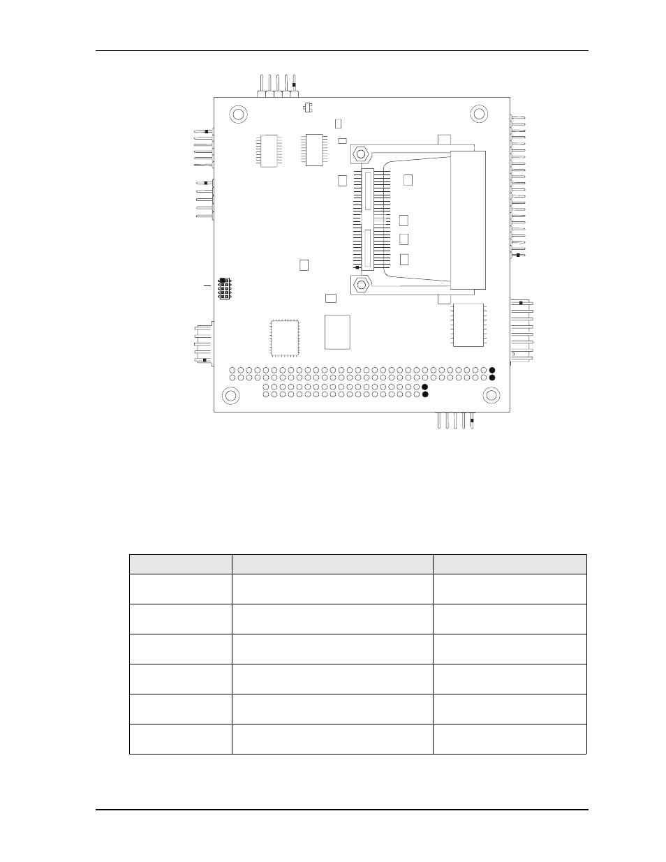
Figure 2-7. Header and Socket Locations (Bottom Side)
Jumper Header Definitions
describes the jumper headers shown in
Note: All jumper headers use .079" (2mm) pitch.
Table 2-3. Jumper Settings
Jumper #
Installed
Removed/Installed
JP1 – Serial Port 2
Termination
Enable RS-485 Termination (Pins 1-2)
Disable RS-485 Termination
(Removed) Default setting
JP2 – Serial Port 1
Termination
Enable RS-485 Termination (Pins 1-2)
Disable RS-485 Termination
(Removed) Default setting
JP5 – Backlight
Voltage Select
+5 Volts (Pins 1-2)
+12 Volts (Pins 2-3) Default
JP6 – Flat Panel
Voltage Select
+3.3 Volts (Pins 1-2) Default
+5 Volts (Pins 2-3)
JP7 – Compact Flash
Voltage Select
+5 Volts (Pins 1-2)
+3.3 Volts (Pins 2-3) Default
JP8 – IDE Select
Enable HDD master, CF slave (Pins 1-2)
Default
Enable HDD slave, CF master
(Pins 2-3)
CM435_conn_bottom_a
J20
Key:
J12 - Compact Flash
J20 - LPC
J12