Table 3-17, Battery ethernet external led miscellaneous, Ssd (solid state drive) real time clock (rtc) – ADLINK CoreModule 745 User Manual
Page 38: External battery input header (j6), Table 3-18, Ethernet external led pin signals (j11), Battery, Ethernet external led, Miscellaneous
Chapter 3
Hardware
32
Reference Manual
CoreModule 745
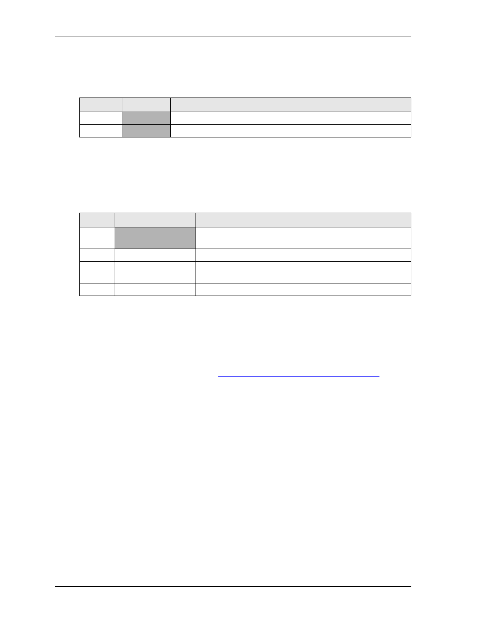
Battery
lists the pin signals of the External Battery Input header for backup CMOS RAM and RTC (Real
Time Clock), which uses 2 pins, single row, with 0.049" (1.25mm) pitch.
Note: The shaded table cells denote power or ground.
Ethernet External LED
This header provides signals for an external LED that indicates Ethernet links and activity using a single row
of 4 pins with 0.049" (1.25mm) pitch.
Note: The shaded table cell denotes power.
Miscellaneous
SSD (Solid State Drive)
The CoreModule 745 provides a standard SSD, which is a storage IC soldered directly onto the board. For
more information, refer to the SSD data sheet:
http://www.greenliant.com/products/?inode=46780
.
Real Time Clock (RTC)
The CoreModule 745 contains a Real Time Clock (RTC). The RTC can be backed up with a battery. If the
battery is not present, the board BIOS has a battery-less boot feature to complete the boot process.
Table 3-17. External Battery Input Header (J6)
Pin #
Signal
Description
1
VBAT_EXT +3.0 volts DC
2
GND Ground
Table 3-18. Ethernet External LED Pin Signals (J11)
Pin #
Signal
Description
1
V3.3_CONN
+3 volts – Provides +3 volts to external LED (Pins 1-2 for Green
LED)
2
ETH_ACT_LED
Ethernet Activity
3
ETH_LINK100_LED
Fast Ethernet Link with +3 volts power (Pins 3-4 for Bi-Color
LED)
4
ETH_LINK1000_LED Gigabit Ethernet Link