Serial interfaces, Figure 3-1, Rs485 serial port implementation – ADLINK CoreModule 745 User Manual
Page 29
Chapter 3
Hardware
CoreModule 745
Reference Manual
23
Serial Interfaces
The CoreModule 745 provides three serial ports: two RS-232/485/422 ports (COM1 and COM2) and one
RS-232 port (COM3). The SCH3114I-NU SIO contains the circuitry for all three serial ports and delivers
the signals through three transceivers. The two RS-232/485/422 ports require two transceivers: one
ADM213EARSZ (U11) for RS-232 signals and one LTC1334CG (U12) for RS-485/422 signals. The third
serial port requires only one ADM213EARSZ transceiver (U38) for RS-232 signals. The serial ports support
the following features:
•
Three individual high-speed NS16C550A-compatible UARTs
•
Programmable word length, stop bits and parity
•
16-bit programmable baud rate generator
•
Interrupt generator
•
Loop-back mode
•
Three individual 16-bit FIFOs
•
Serial Port Headers
J3 - Serial Port 1 (COM1) supports RS-232/RS-485/RS-422 and full modem support
J4 - Serial Port 2 (COM2) supports RS-232/RS-485/RS-422 and full modem support
J5 - Serial Port 3 (COM3) supports RS-232 and full modem support
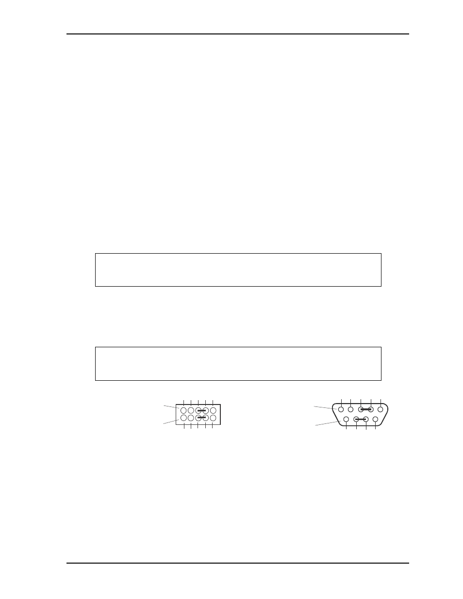
To implement the two-wire RS-485 mode on any serial port, you must tie together the equivalent pins for
each port.
For example, on Serial Port 1, tie pin 3 to 5 and pin 4 to 6 at the J3 header as shown in
. As an
alternate, tie pin 2 to 3 and pin 7 to 8 at the DB9 serial connector for Serial Port 1 as shown in
.
Refer also to the following tables for the specific pin signals on each connector.
Figure 3-1. RS485 Serial Port Implementation
NOTE
The RS-485/RS-422 mode can be selected for the COM1 and COM2 serial ports
in BIOS Setup under the Advanced>Super IO Configuration menu. However,
the RS-232 mode is the default selection (Standard) for any serial port.
NOTE
The RS-422 mode uses a four-wire interface and does not require any pins tied
together, but you must select RS-485 in BIOS Setup and make sure the
termination jumper is removed.
CM745RS485jump_b
Or
1
3
5
7
9
2
4
6
8
10
Serial Ports
COM1 and COM2
(J3 and J4)
Standard DB9 Serial
Port Connector (Female)
Rear View
5
4
3
2
1
9
8
7
6