Figure 2-6, Header, connector, and socket locations (top side) – ADLINK CoreModule 745 User Manual
Page 18
Chapter 2
Product Overview
12
Reference Manual
CoreModule 745
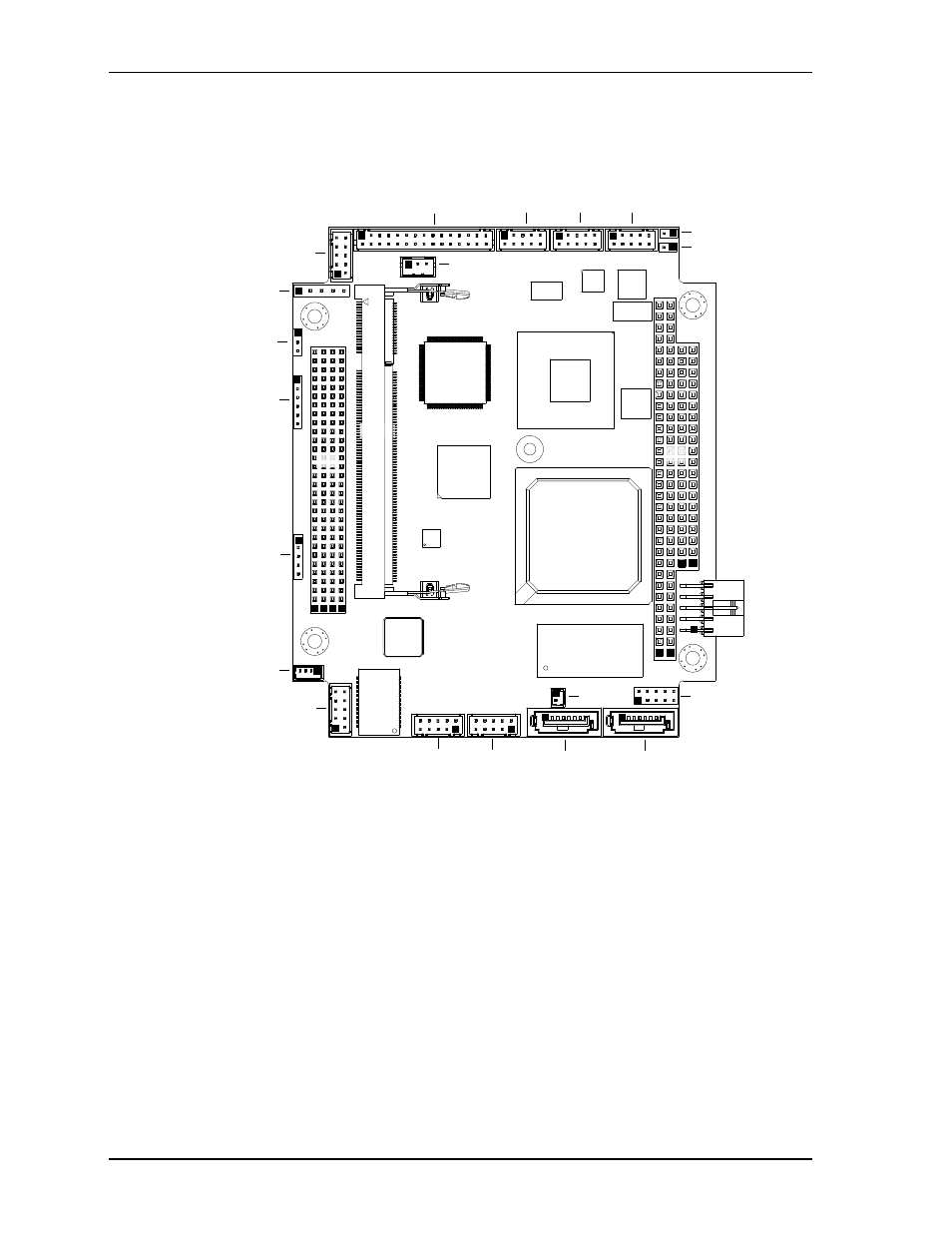
Figure 2-6. Header, Connector, and Socket Locations (Top Side)
CM745_T
op_Conn_b
Key:
J1 - PC/104 Plus
J2 - PC/104
J3 - Serial COM1
J4 - Serial COM2
J5 - Serial COM3
J6 - Battery
J7 - Power
J8 - SATA0
J9 - SATA1
J10 - Gigabit Ethernet
J11 - Gigabit Ethernet LED
J12 - Not supported (On bottom side)
J14 - Do Not Populate
J15 - Keyboard and Mouse
J16 - USB0 and USB1
J17 - USB2 and USB3
J18 - GPIO
J19 - Video (LVDS and VGA)
J20 - SMBus
J22 - Fan
J23 - Utility
J24 - DDR3 SODIMM
JP2 - LVDS Voltage Select (See jumper table)
JP3 - Serial 2 RS-485/422 Termination (See jumper table)
JP4 - Serial 1 RS-485/422 Termination (See jumper table)
J20
J11
J14
JP2
J23
J22
J7
J9
J8
J18
J6
JP3
JP4
J4
J3
J15
J19
J5
J10
J16
J17
J1
J2
J24
DCBA
BA
CD
See also other documents in the category ADLINK Hardware:
- USB-1901 (84 pages)
- USB-1210 (54 pages)
- USB-2401 (60 pages)
- USB-7230 (50 pages)
- USB-2405 (56 pages)
- DAQe-2010 (92 pages)
- DAQe-2204 (100 pages)
- DAQe-2213 (94 pages)
- DAQe-2501 (74 pages)
- PXI-2010 (84 pages)
- PXI-2020 (60 pages)
- PXI-2501 (62 pages)
- cPCI-9116 (98 pages)
- ACL-8112 Series (93 pages)
- ACL-8112 Series (94 pages)
- ACL-8112 Series (92 pages)
- ACL-8216 (75 pages)
- ACL-8111 (61 pages)
- PCM-9112+ (10 pages)
- PCM-9112+ (94 pages)
- cPCI-6216V (47 pages)
- ACL-6126 (28 pages)
- ACL-6128A (40 pages)
- PCM-6308V+ (52 pages)
- PCM-6308V+ (4 pages)
- PCI-7444 (82 pages)
- PCI-7434 (48 pages)
- PCI-7234 (56 pages)
- PCI-7260 (66 pages)
- PCI-7258 (38 pages)
- PCI-7256 (48 pages)
- PCI-7250 (48 pages)
- LPCI-7250 (48 pages)
- PCI-7396 (65 pages)
- PCI-7296 (59 pages)
- PCI-8554 (67 pages)
- PCIe-7360 (94 pages)
- PCIe-7350 (86 pages)
- PCIe-7300A (114 pages)
- PCIe-7200 (51 pages)
- PCI-7300A (112 pages)
- PCI-7300A (83 pages)
- PCI-7200 (96 pages)
- cPCI-7300 (82 pages)
- cPCI-7300 (83 pages)