Table 3-15, Table 3-14, System management bus (smbus) system fan – ADLINK CoreModule 745 User Manual
Page 37: Table 3-13, Utility interface pin signals (j23), Smbus reserved addresses, Smbus pin signals (j20), Table 3-16, Optional system fan pin signals (j22), System management bus (smbus)
Chapter 3
Hardware
CoreModule 745
Reference Manual
31
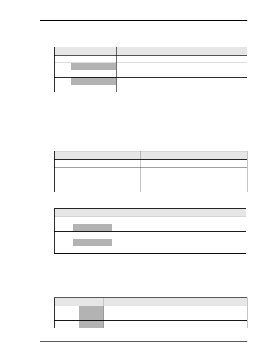
describes the pin signals of the Utility interface, which uses a 5-pin, single-row header with
0.100" (2.54mm) pitch.
Note: The shaded table cells denote power or ground. The * symbol indicates the signal is Active Low.
System Management Bus (SMBus)
The ICH8-M chip contains a host SMBus port. The host port allows the CPU access to the SMBus slaves
through header, J20. The SMBus slaves include the SODIMM EPROM, Clock Buffer, Clock Generator, and
the Gb Ethernet Controller.
lists the device names and corresponding reserved binary addresses
on the SMBus.
lists the SMBus pin signals, which are routed through a 5-pin, single-row header
with 0.049" (2 mm) pitch.
Note: The shaded table cells denote power or ground. The * symbol indicates the signal is Active Low.
System Fan
lists the pin signals of the optional System Fan header, which provides 3 pins with 0.079" (2mm)
pitch.
Note: The shaded table cells denote power or ground.
Table 3-13. Utility Interface Pin Signals (J23)
Pin #
Signal
Description
1
/PWR_BTN*
External Power Button (Pins 1-2)
2
GND
Ground
3
/RESET SW*
External Reset Switch signal (Pins 2-3)
4
5V
+5 Volts Power
5
SPKR_CONN
Speaker Output (Pins 4-5)
Table 3-14. SMBus Reserved Addresses
Component
Address Binary
SODIMM EPROM
1010,000x
b
Clock Generator
1101,001x
b
Clock Buffer
1101,110x
b
Gb Ethernet Controller
1100,001x
b
Table 3-15. SMBus Pin Signals (J20)
Pin #
Signal
Description
1
SMB_CLK
SMBus Clock
2
GND
Ground
3
SMB_DATA
SMBus Data
4
VSM
+3.3V standby voltage
5
/SMB_ALERT*
SMBus Alert
Table 3-16. Optional System Fan Pin Signals (J22)
Pin #
Signal
Description
1
VCC
+5.0 volts DC +/- 5%
2
NC
Not Connected
3
GND Ground