Block diagram, Figure 2-2, Functional block diagram – ADLINK CoreModule 745 User Manual
Page 13: Coremodule 745 reference manual 7, Figure 2-2. functional block diagram
Chapter 2
Product Overview
CoreModule 745
Reference Manual
7
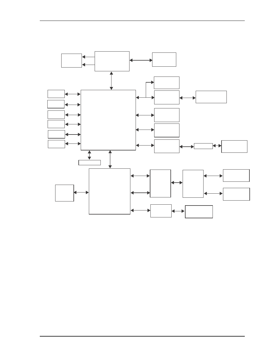
Block Diagram
shows the functional components of the CoreModule 745.
Figure 2-2. Functional Block Diagram
CM745BlkDiag_b
PC/104
PCI to ISA
Connector
Bridge
IT8888G-L
CPU
Intel Atom 1.67GHz
N455 or 1.83GHz D525
(with integrated
Northbridge)
PC/104-Plus
Connector
I/O Hub
Intel
ICH8-M
(Southbridge)
PS/2
Keyboard/
Mouse
Header
Super I/O
SCH3112I-NU
DDR3
SODIMM
Video Header
VGA
LVDS
Memory Bus
ISA Bus
LPC Bus
COM2
Header
(RS-232/485/422)
COM1
Header
(RS-232/485/422)
RS-232
Transceiver
(COM1
and COM2)
RS-485/422
Transceiver
(COM1
and COM2)
PCI Bus
DMI
USB
Header
USB
Header
USB (2)
USB (2)
Serial 1
Serial 2
Serial 3
PS/2
SPI Flash
GPIO
Header
SATA
SATA
IDE
SMBus
SPI
GPIO
SMBus
Header
Utility Header
Solid State
Drive
SATA0
Connector
SATA1
Connector
RS-232
Transceiver
(COM3)
COM3
Header
(RS-232)
Magnetics
Gigabit Ethernet
Controller
82574IT
Gigabit Ethernet
Header
MDI
PCIe Bus