Power interface, Table 3-11, Power interface pin signals (j7) – ADLINK CoreModule 745 User Manual
Page 35
Chapter 3
Hardware
CoreModule 745
Reference Manual
29
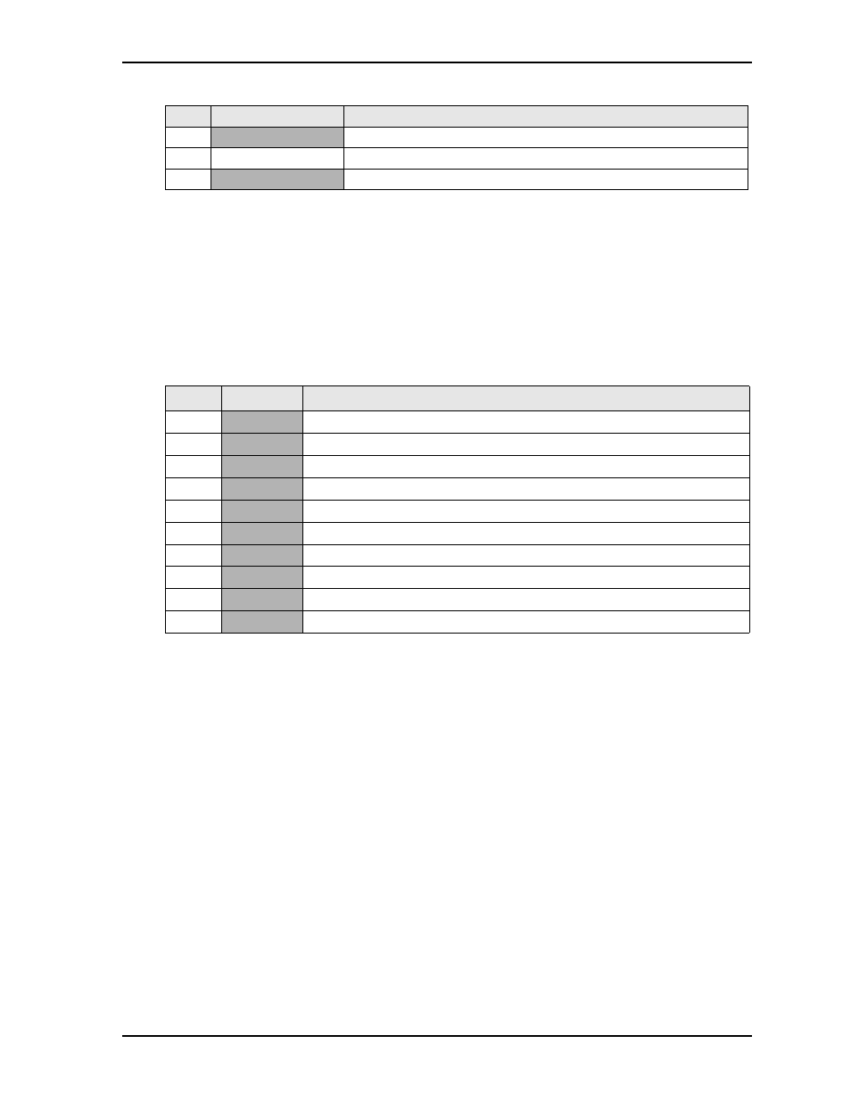
Note: The shaded table cells denote power or ground.
Power Interface
The CoreModule 745 requires one +5 volt DC power source and provides a shrouded 10-pin, right-angle
header with 2 rows, odd/even pin sequence (1, 2), and 0.100" (2.54mm) pitch. If the +5VDC power drops
below ~4.65V, a low voltage reset is triggered, resetting the system.
The power input header (J7) supplies the following voltage and ground directly to the module:
•
5.0VDC +/- 5%
Note: The shaded table cells denote power or ground.
28
GND VGA
VGA Ground
29
CRT_VSYNC
Vertical Sync – Digital Vertical Sync Output to the CRT
30
VCC_CON_DAC
+5V Power and Ground for Digital to Analog Converter
Table 3-11. Power Interface Pin Signals (J7)
Pin
Signal
Descriptions
1
GND Ground
2
+5V
+5 Volts
3
GND
Ground
4
+12V +12
Volts
routed
to PC/104, PC/104-Plus, and LVDS interfaces
5
GND
Ground
6
+3.3V_PCI
+3.3 Volts routed to PCI
7
GND
Ground
8
+5V
+5 Volts
9
GND
Ground
10
+5V
+5 Volts
Table 3-10. Video Interface Pin Signals (J19) (Continued)
Pin # Signal
Description