User gpio interface utility interface, Power button reset switch speaker, Table 3-12 – ADLINK CoreModule 745 User Manual
Page 36: User gpio interface pin signal descriptions (j18), User gpio interface, Utility interface
Chapter 3
Hardware
30
Reference Manual
CoreModule 745
User GPIO Interface
The CoreModule 745 provides GPIO pins for customer use, routing the signals from the ICH8-M chipset to
the J18 header. An example test application and source code reside in each BSP directory of the
CoreModule 745 Support Software QuickDrive.
For instructions on using the example applications, refer to the GPIO Readme in each BSP directory of the
QuickDrive. For more information about the GPIO pin operation, refer to the ICH8-M datasheet at:
http://www.intel.com/assets/pdf/datasheet/313056.pdf
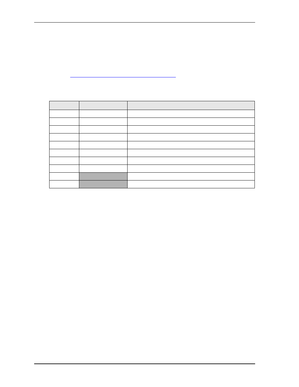
describes the pin signals of the GPIO interface, which consists of a 10-pin header with 2 rows,
odd/even pin sequence (1, 2), and 0.079" (2mm) pitch.
Note: The shaded table cells denote ground.
Utility Interface
The Utility interface provides three I/O signals on the module and consists of a 5-pin, 0.100" (2.54mm),
single-row header (J23). The ICH8-M drives the Power Button and Speaker signals on the Utility interface.
A separate Power Management microprocessor drives the Reset Switch signal.
provides the
signal definitions.
•
Power Button
•
Reset Switch
•
Speaker
Power Button
The Utility header provides a signal for an external Power Button through pins 1 and 2. The Power Button
allows the user to shut down and power on the system. To shut down the system, press and hold the Power
Button for four seconds. Press the Power Button for one second to power on the system.
Reset Switch
Pins 2 and 3 on the Utility header provide the signal for an external reset button which allows the user to re-
boot the system.
Speaker
The speaker signal provides sufficient signal strength to drive a 1W 8
“Beep” speaker at an audible level
through pins 4 and 5 on the Utility header. The speaker signal is driven from an on-board amplifier and the
ICH8-M.
Table 3-12. User GPIO Interface Pin Signal Descriptions (J18)
Pin #
Signal from ICH8-M Description
1 - GPI1
GPIO1
User defined
2 - GPO1
GPIO17
User defined
3 - GPI2
GPIO6
User defined
4 - GPO2
GPIO18
User defined
5 - GPI3
GPIO7
User defined
6 - GPO3
GPIO20
User defined
7 - GPI4
GPIO8
User defined
8 - GPO4
GPIO27
User defined
9
GND
Ground
10
GND
Ground