Table 2-3, Jumper header definitions, Figure 2-7 – ADLINK CoreModule 745 User Manual
Page 19: Jumper header locations (top side), Jumper settings
Chapter 2
Product Overview
CoreModule 745
Reference Manual
13
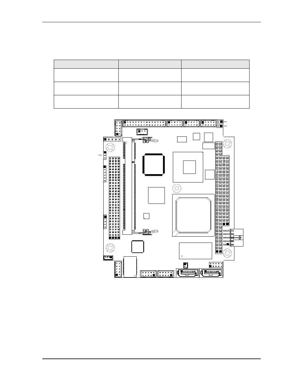
Jumper Header Definitions
describes the jumper headers shown in
. All jumper headers provide 0.079" (2mm)
pitch.
Figure 2-7. Jumper Header Locations (Top Side)
Table 2-3. Jumper Settings
Jumper Header
Installed
Removed/Installed
JP2 – LVDS Voltage Selection
Enable +3.3V (Pins 1-2)
[Default]
Enable +5V (Pins 2-3)
JP3 – Serial 2 RS-485/422
Termination
Enable Termination
(Pins 1-2)
Disable Termination (Removed)
[Default]
JP4 – Serial 1 RS-485/422
Termination
Enable Termination
(Pins 1-2)
Disable Termination (Removed)
[Default]
CM745_T
op_Jmpr_b
Key:
JP2 - LVDS Voltage Select
JP3 - Serial 2 RS-485/422 Termination
JP4 - Serial 1 RS-485/422 Termination
JP2
JP3
JP4
See also other documents in the category ADLINK Hardware:
- USB-1901 (84 pages)
- USB-1210 (54 pages)
- USB-2401 (60 pages)
- USB-7230 (50 pages)
- USB-2405 (56 pages)
- DAQe-2010 (92 pages)
- DAQe-2204 (100 pages)
- DAQe-2213 (94 pages)
- DAQe-2501 (74 pages)
- PXI-2010 (84 pages)
- PXI-2020 (60 pages)
- PXI-2501 (62 pages)
- cPCI-9116 (98 pages)
- ACL-8112 Series (94 pages)
- ACL-8112 Series (92 pages)
- ACL-8112 Series (93 pages)
- ACL-8216 (75 pages)
- ACL-8111 (61 pages)
- PCM-9112+ (10 pages)
- PCM-9112+ (94 pages)
- cPCI-6216V (47 pages)
- ACL-6126 (28 pages)
- ACL-6128A (40 pages)
- PCM-6308V+ (52 pages)
- PCM-6308V+ (4 pages)
- PCI-7444 (82 pages)
- PCI-7434 (48 pages)
- PCI-7234 (56 pages)
- PCI-7260 (66 pages)
- PCI-7258 (38 pages)
- PCI-7256 (48 pages)
- PCI-7250 (48 pages)
- LPCI-7250 (48 pages)
- PCI-7396 (65 pages)
- PCI-7296 (59 pages)
- PCI-8554 (67 pages)
- PCIe-7360 (94 pages)
- PCIe-7350 (86 pages)
- PCIe-7300A (114 pages)
- PCIe-7200 (51 pages)
- PCI-7300A (112 pages)
- PCI-7300A (83 pages)
- PCI-7200 (96 pages)
- cPCI-7300 (83 pages)
- cPCI-7300 (82 pages)