Chapter 2, Product overview, Etx computer-on-module concept – ADLINK ETX-PVR User Manual
Page 9: Figure 2-1, Etx-pvr module and custom baseboard assembly, Chapter 2 product overview
ETX-PVR
Reference Manual
3
Chapter 2
Product Overview
This introduction presents general information about the ETX Architecture and the ETX-PVR Computer-
on-Module (COM). After reading this chapter you should understand:
•
ETX Computer-on-Module concept
•
ETX-PVR product description
•
ETX-PVR features
•
Major components
•
Connectors
•
Specifications
ETX Computer-on-Module Concept
Embedded system designers face increasing pressures to bring products to market quickly. Many products
that once incorporated a custom CPU design can no longer afford the time to develop and debug a custom
CPU let alone port operating system software to it. Furthermore, CPU subsystem design usually plays a
small part in providing any uniqueness to an embedded product. The remainder of the embedded product
design adds key circuits that provide a unique product and differentiate it from other products serving the
same market. The challenge is to speed these designs to market by eliminating the need for a custom CPU
design while providing the flexibility to include all critical elements, which make the embedded product
unique.
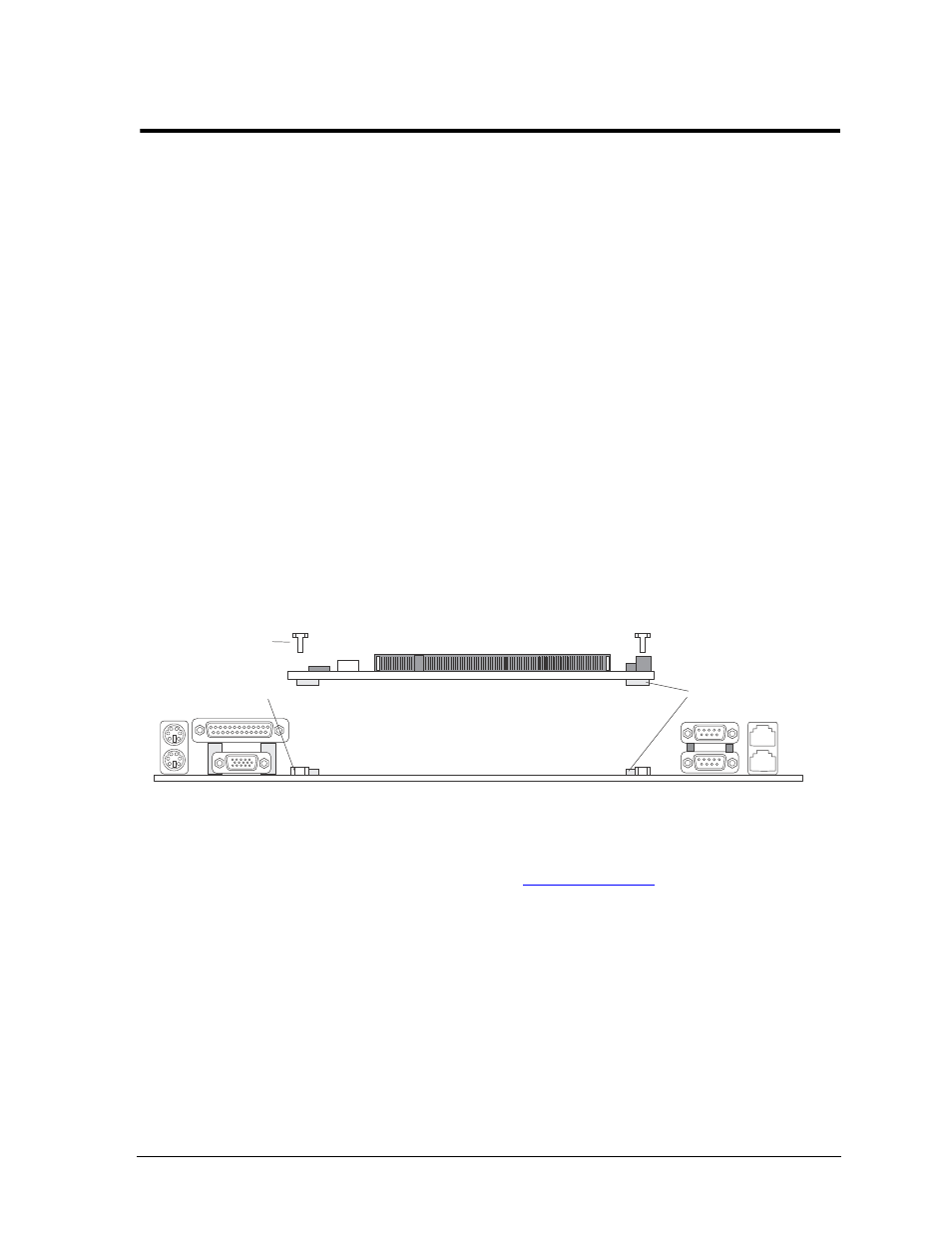
The Embedded Technology eXtended (ETX) module provides an off-the-shelf CPU subsystem that can be
included in virtually any embedded system. An ETX module works like a high-integration chip, plugging
into your custom circuit board design to provide specific control for your logic application. See
Figure 2-1
.
Figure 2-1. ETX-PVR Module and Custom Baseboard Assembly
ETX provides a simple, standard interface that is independent of CPU type. The ETX interface includes the
industry-standard PCI bus, ISA bus (some models), I/O signals from the peripheral components on the ETX
module, power, and ground. Visit the ADLINK web site (
www.adlinktech.com
) for the latest ETX processor
availability and support information.
The standard ETX interface lets you try different processors in your actual product environment with the
ability to defer a processor choice until late in the project if you so choose. The interface also lets you easily
offer different versions of your product with different capabilities by either selecting different ETX modules
with the same baseboard, or by designing different baseboards for the same CPU. This simple ability to
upgrade by either selecting a more powerful CPU (without baseboard redesign) or enhancing the baseboard
without touching the CPU subsystem or the bulk of the applications software.
The ETX flexibility enables designers to take an accelerated, low risk path by using proven ETX module
designs. Your design flow might look similar to the one shown in
Figure 2-2
. This diagram gives a Typical
Design Flow of hardware and software functions.
ETX-PVR_Stack
ETX-PVR Computer -on -Module
Custom Baseboard Design
Stack Connectors
(4 pairs)
M2.5 PEM Nuts
Spacing 3 mm (4)
M2.5 Screws (4)