ADLINK ETX-PVR User Manual
Page 36
Chapter 3
Hardware
30
Reference Manual
ETX-PVR
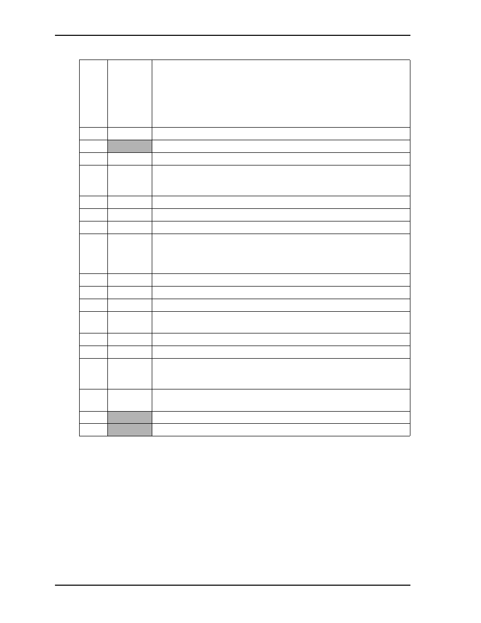
Note: The shaded areas denote power or ground. The * symbol indicates the signal is Active Low.
81
IOCHRDY I/O Channel Ready – This signal allows slower ISA boards to lengthen I/O or
memory cycles by inserting wait states. This signal’s normal state is active high
(ready). ISA boards drive the signal inactive low (not ready) to insert wait
states. Devices using this signal to insert wait states should drive it low
immediately after detecting a valid address decode and an active read, or write
command. The signal is released high when the device is ready to complete the
cycle.
82 NS
Not
Supported
83, 84
VCC
DC Power – +5 volts +/- 5%
85
SD0
System Data 0 – Refer to SD14, pin-3 for more information.
86
SMEMW*
System Memory Write – This signal is used by bus owner to request a memory
device to store data currently on the data bus and only active for the lower
1 MB. Used for legacy compatibility with 8-bit cards.
87
SD2
System Data 2 – Refer to SD14, pin-3 for more information.
88
SD1
System Data 1 – Refer to SD14, pin-3 for more information.
89
SD3
System Data 3 – Refer to SD14, pin-3 for more information.
90
NOWS*
No Wait State – This signal is driven low by a bus slave device to indicate it is
capable of performing a bus cycle without inserting any additional wait states.
To perform a 16-bit memory cycle without wait states, this signal is derived
from an address decode.
91 NS
Not
Supported
92
SD4
System Data 4 – Refer to SD14, pin-3 for more information.
93
SD5
System Data 5 – Refer to SD14, pin-3 for more information.
94
IRQ9
Interrupt Request 9 – Asserted by a device when it has pending interrupt
request. Only one device may use the request line at a time.
95
SD6
System Data 6 – Refer to SD14, pin-3 for more information.
96
SD7
System Data 7 – Refer to SD14, pin-3 for more information.
97
IOCHK*
I/O Channel Check – This signal may be activated by ISA boards to request that
a non-maskable interrupt (NMI) be generated to the system processor. It is
driven active to indicate an uncorrectable error has been detected.
98
RSTDRV
Reset Drive – This signal is used to reset or initialize system logic on power up
or subsequent system reset.
99
GND
Ground
100
GND
Ground
Table 3-5. Complete X2 ISA Bus Interface Pin Signal Descriptions (J2) (Continued)