Miscellaneous, Oops! jumper (bios recovery) remote access, Remote access setup hot (serial) cable – ADLINK ETX-PVR User Manual
Page 48: Temperature monitoring, Figure 3-1, Oops! jumper connection, Figure 3-2, Hot cable jumper
Chapter 3
Hardware
42
Reference Manual
ETX-PVR
Miscellaneous
Oops! Jumper (BIOS Recovery)
The Oops! jumper is provided in the event the BIOS settings you have selected prevent you from booting the
system. By using the Oops! jumper you can prevent the current BIOS settings in the Flash memory from
being loaded, forcing the use of the default settings. Connect the DTR pin to the RI pin on serial port 1
(COM 1) on the baseboard prior to boot up to prevent the present BIOS settings from loading. After booting
with the Oops! jumper in place, remove the Oops! jumper from the baseboard connector and enter the BIOS
Setup Utility. Change the desired BIOS settings or select the default settings and save changes before
rebooting the system.
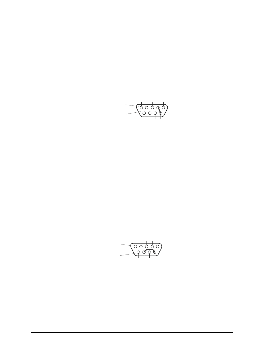
To convert a standard DB9 connector to an Oops! jumper for use on the custom baseboard, short together the
DTR (4) and RI (9) pins on the rear of the connector for Serial Port 1 as shown in
Figure 3-1. Oops! Jumper Connection
Remote Access
The BIOS Setup Utility supports the Remote Access (or console redirection) feature. This I/O function can
be utilized through an ANSI-compatible serial terminal or the equivalent terminal emulation software
running on another system. This can be very useful when setting up the BIOS on a production line for
systems that are not connected to a keyboard and display.
Remote Access Setup
The Remote Access feature is implemented by connecting a standard null modem cable or modified serial
cable (“Hot Cable”) between one of the serial ports (Serial 1 or 2) and the serial terminal or a PC with
communications software. The BIOS Setup Utility controls the Remote Access settings on the ETX-PVR.
Refer to
“BIOS Advanced Setup Screen” on page 50
in Chapter 4, for the settings of the Remote Access
feature.
Hot (Serial) Cable
To convert a standard serial cable to a Hot Cable for use on the custom baseboard, two pins must be shorted
together at the Serial port DB9 connector. Short together the RTS (7) and RI (9) pins on Serial port DB9
connector as shown in
.
Figure 3-2. Hot Cable Jumper
Temperature Monitoring
The temperature monitoring function is performed by the ADT7481 temperature sensor, which takes inputs
from the thermal diodes in the CPU. The ADT7481 chip uses the two-wire SMBus interface to communicate
with the other devices, taking temperature readings and issuing alerts to the ICH when a reading surpasses
over or under temperature limits. Refer to the ADT7481 data sheet for more information at:
http://www.onsemi.com/pub_link/Collateral/ADT7481-D.PDF
.
ETX-PVR_Oopsjump
Standard DB9 Serial
Port Connector (Female)
Rear View
5
4
3
2
1
9
8
7
6
ETX-PVR_HotCable
Standard DB9 Serial
Port Connector (Female)
Rear View
5
4
3
2
1
9
8
7
6