ADLINK ETX-PVR User Manual
Page 39
Chapter 3
Hardware
ETX-PVR
Reference Manual
33
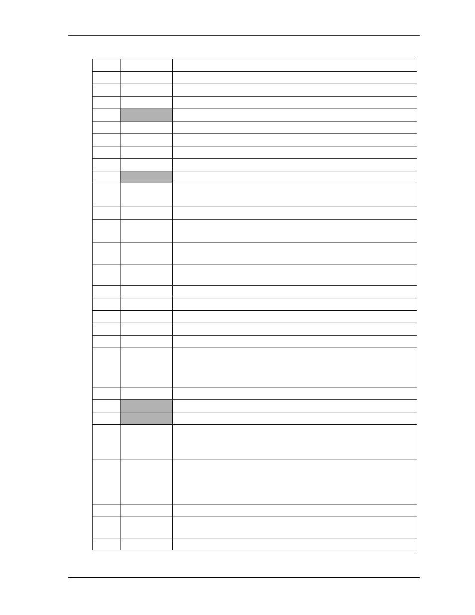
29
LCDDO4
Data Negative Output, Line 2, Channel 1
30
LCDDO7
Clock Positive Output, Clock, Channel 1
31
LCDDO5
Data Positive Output, Line 2, Channel 1
32
LCDDO6
Clock Negative Output, Clock, Channel 1
33, 34 GND
Ground
35
LCDDO1
Data Positive Output, Line 0, Channel 1
36
LCDDO3
Data Positive Output, Line 1, Channel 1
37
LCDDO0
Data Negative Output, Line 0, Channel 1
38
LCDDO2
Data Negative Output, Line 1, Channel 1
39, 40 VCC
DC Power – +5V +/- 5%
41 JILI_DAT
Flat Panel I
2
C Data – This is the I
2
C data interface to the parameter
EEPROM used with the flat panel.
42 LTGIO0
General
Purpose
I/O
43 JILI_CLK
Flat Panel I
2
C Clock – This is the I
2
C clock interface to the parameter
EEPROM used with the flat panel.
44
BLON*
Backlight On – This signal controls the external backlight power for the flat
panel.
45 BIASON
(DNP)
BIAS ON – This signal controls the flat panel contrast voltage.
46
DIGON
Digital Power On – This signal controls the digital flat panel power up.
47 NC
Not
Connected
48 NC
Not
Connected
49 NC
Not
Connected
50 NC
Not
Connected
51
LPT/FLPY*
Parallel/Floppy Select – This signal selects the parallel or floppy port
signals. If this signal is Low at boot time, the floppy drive is selected. If this
signal is High at boot time, the parallel port is selected. This state can not be
changed until the next boot cycle.
52 NC
Not
Connected
(Reserved)
53
VCC
DC Power – +5 volts +/- 5%
54
GND
Ground
55 Strobe*
DS0*
Parallel Strobe – This output signal is used to strobe data into the printer. I/O
pin in ECP/EPP mode.
Floppy Drive Select 0 – Selects drive 0.
56 AFD*
DENSEL
Parallel Auto Feed – This is a output signal from the printer to
automatically feed one line after each line is printed.
Floppy Drive Density Select – This signal indicates if a low (250/300 kbps)
or high (500/1 kbps) data rate is selected.
57 NC
Not
Connected
(Reserved)
58
PD7
Parallel Port Data 7 – This signal (0 to 7) provides a parallel port data signal
and is the printer data MSB.
59 NS
Not
Supported
Table 3-6. Complete X3 Interface Pin Signal Descriptions (J3) (Continued)