Lvds interface, Table 3-6, Complete x3 interface pin signal descriptions (j3) – ADLINK ETX-PVR User Manual
Page 38
Chapter 3
Hardware
32
Reference Manual
ETX-PVR
LVDS Interface
The CPU provides direct LVDS outputs, which support a single channel 18-bit LVDS interface with three
signal lines. The N455 CPU provides digital LVDS resolution up to 1280x800, and the D525 CPU provides
resolutions up to 1366x768.
describes the pin signals of the X3 ETX interface connector.
NOTE
The necessary voltages to drive a flat panel are not supplied through the J3 connector
on the ETX-PVR module. The required drive voltages for the flat panel must be
designed into the customer’s baseboard and supplied from the ATX or AT power
supply to provide drive voltages for the LVDS connector to the flat panel.
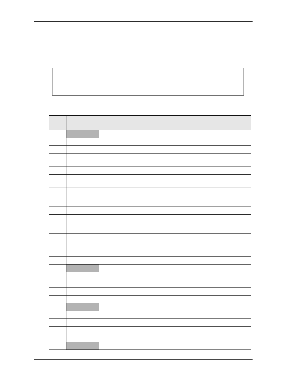
Table 3-6. Complete X3 Interface Pin Signal Descriptions (J3)
J3
Pin #
Signal
Description
1, 2
GND
Ground
3
Red
Red – This is the Red analog output signal to the CRT.
4
Blue
Blue – This is the Blue analog output signal to the CRT.
5
HSYNC
Horizontal Sync – This signal is used for the digital horizontal sync output
to the CRT.
6
Green
Green – This is the Green analog output signal to the CRT.
7
VSYNC
Vertical Sync – This signal is used for the digital vertical sync output to the
CRT.
8
DDCK
Display Data Channel Clock – This signal line provides the data clock signal
to the Memory Hub from the monitor. This is part of the Plug and Play
standard developed by the VESA trade association.
9 NC
Not
Connected
10
DDDA
Display Data Channel Data – This signal line provides information to the
Memory Hub about the monitor type, brand, model. This is part of the Plug
and Play standard developed by the VESA trade association.
11 NC
Not
Connected
12 NC
Not
Connected
13 NC
Not
Connected
14 NC
Not
Connected
15, 16 GND
Ground
17 NC
Not
Connected
18 NC
Not
Connected
19 NC
Not
Connected
20 NC
Not
Connected
21, 22 GND
Ground
23 NC
Not
Connected
24 NC
Not
Connected
25 NC
Not
Connected
26 NC
Not
Connected
27, 28 GND
Ground