ADLINK ETX-PVR User Manual
Page 47
Chapter 3
Hardware
ETX-PVR
Reference Manual
41
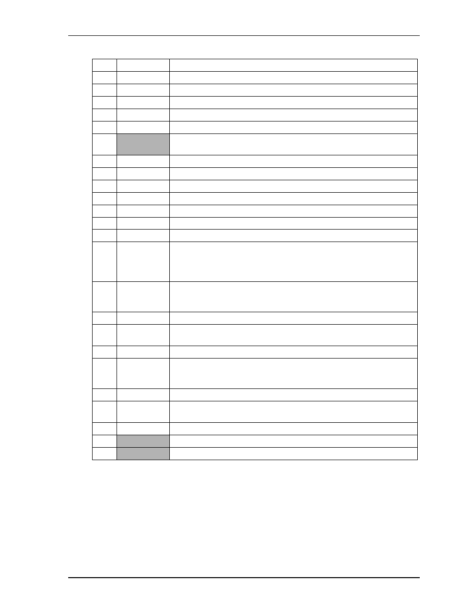
Note: The shaded areas denote power or ground. The * symbol indicates the signal is Active Low.
75 NC
Not
Connected
76
PIDE_D11
Primary Disk Data 11 – Refer to J4, pin-58 for more information.
77 NC
Not
Connected
78
PIDE_D4
Primary Disk Data 4 – Refer to J4, pin-58 for more information.
79 NC
Not
Connected
80
PIDE_D10
Primary Disk Data 10 – Refer to J4, pin-58 for more information.
81,
82
VCC
DC Power – +5 volts +/-5%
83 NC
Not
Connected
84
PIDE_D5
Primary Disk Data 5 – Refer to J4, pin-58 for more information.
85 NC
Not
Connected
86
PIDE_D9
Primary Disk Data 9 – Refer to J4, pin-58 for more information.
87 NC
Not
Connected
88
PIDE_D6
Primary Disk Data 6 – Refer to J4, pin-58 for more information.
89 NC
Not
Connected
90
CBLID
Cable ID Select – Used to detect the presence of an 80 conductor IDE cable
on the primary IDE channel. This allows BIOS or system software to
determine if it is necessary to enable the high-speed transfer modes (DMA66
or DMA100).
91
RXD-
Half of Ethernet Analog Twisted Pair Receive Differential Pair – This pin and
pin-93 make up the Receive twisted pair and receive the serial bit stream on
the Unshielded Twisted Pair Cable (UTP).
92
PIDE_D8
Primary Disk Data 8 – Refer to J4, pin-58 for more information.
93
RXD+
Part of Ethernet Analog Twisted Pair Receive Differential Pair – Refer to pin-
91 for more information.
94 NC
Not
Connected
95
TXD-
Half of Ethernet Analog Twisted Pair Transmit Differential Pair – This pin
and pin-97 make up the Transmit twisted pair and transmit the serial bit
stream on the Unshielded Twisted Pair Cable (UTP).
96
PIDE_D7
Primary Disk Data 7 – Refer to J4, pin-58 for more information.
97
TXD+
Part of Ethernet Analog Twisted Pair Transmit Differential Pair – Refer to
pin-95 for more information.
98
HDRST*
Hard Reset – Low active hardware reset (RSTDRV inverted)
99
GND
Ground
100
GND
Ground
Table 3-8. Complete X4 Interface Pin Signal Descriptions (J4) (Continued)