Interrupt channel assignments, Table 3-1 – ADLINK Express-CBR User Manual
Page 24
Chapter 3
Hardware
20
Reference Manual
Express-CBR
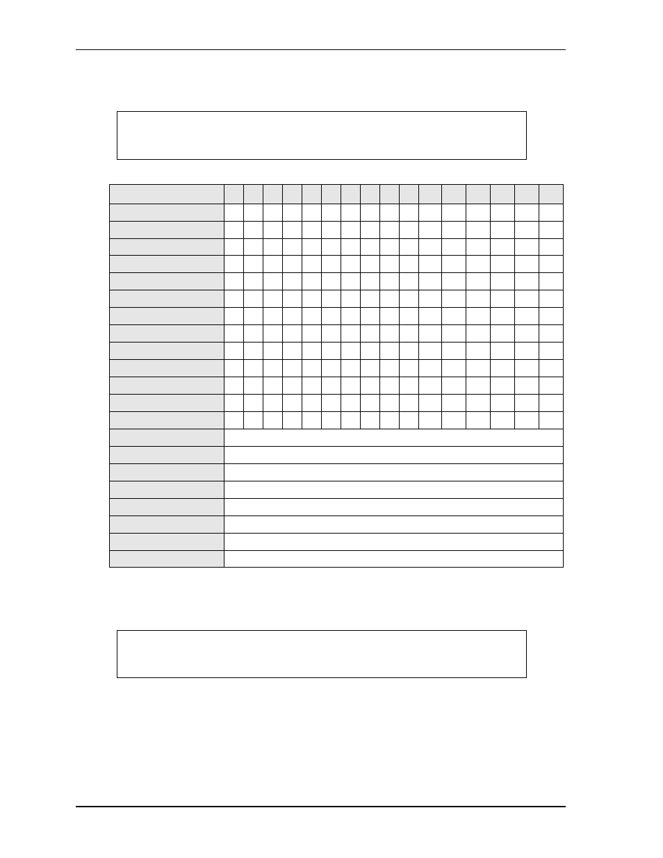
Interrupt Channel Assignments
The interrupt channel assignments are shown in
*Located on the baseboard.
**Located only on the EBX baseboard.
Legend: D = Default, X = Fixed, O = Optional
NOTE
is only for reference. Interrupt channel assignments are tied to the
specific legacy Super I/O device residing on the baseboard. This table can be
used with the baseboard in ADLINK’s Quick Start Kit.
Table 3-1. Interrupt Channel Assignments
Device vs IRQ No.
0
1
2
3
4
5
6
7
8
9
10
11
12
13
14
15
Timer X
Keyboard*
X
Secondary Cascade
X
COM1*
O D
COM2*
D O
COM3**
O
O O
D
COM4**
O
O D
O
Floppy*
D
Parallel*
O
D
RTC
X
IDE
D
O
Math Coprocessor
X
PS/2 Mouse*
X
Audio Controller
Automatically Assigned
PCI INTA
Automatically Assigned
PCI INTB
Automatically Assigned
PCI INTC
Automatically Assigned
PCI INTD
Automatically Assigned
USB
Automatically Assigned
VGA
Automatically Assigned
Ethernet
Automatically Assigned
NOTE
The IRQs for the Ethernet, Video, and USB are automatically assigned by the
BIOS Plug and Play logic. Local IRQs assigned during initialization can not be
used by external devices.