Tilt lock screw black liner, Installation manual, Visix network camera – 3xLOGIC VISIX Camera User Manual
Page 55
Installation Manual
|
VISIX Network Camera
10225 Westmoor Drive, Suite 300, Westminster, CO 80021 | www.3xlogic.com | (877) 3XLOGIC
54
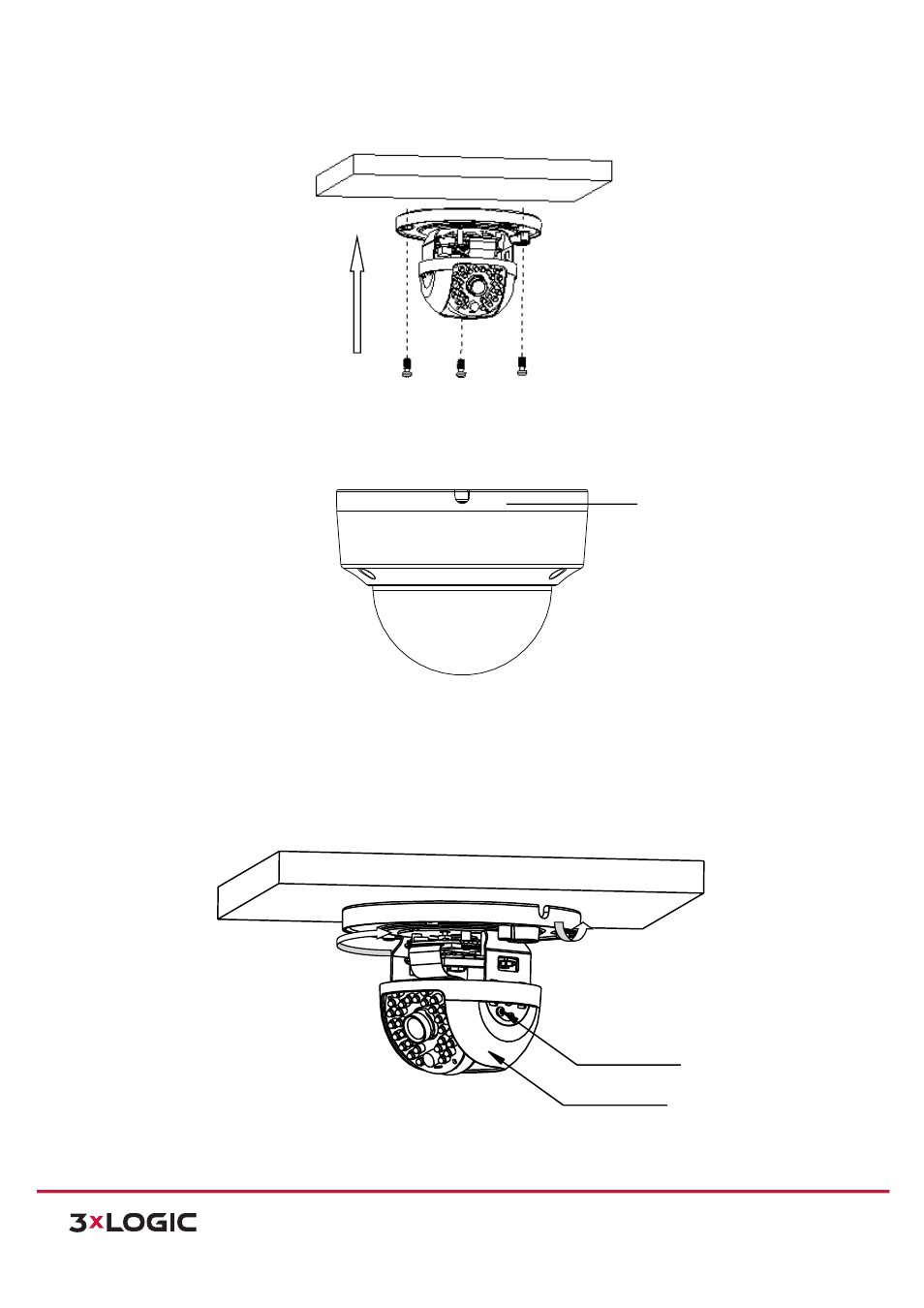
3) Attach the mounting base on the ceiling with screws.
Figure 6-‐4
Attach the Mounting Base
NOTE:
If required, you can route cables through the side opening on the side of the mounting base.
Figure 6-‐5
Side Opening
4) Loosen the tilt lock screws, adjust the tilting position in a range of 65 degrees, and tighten the tilt lock
screws.
5) Rotate the black liner to adjust the panning position in a range of 180 degrees until you get the
desired surveillance angle.
Figure 6-‐6
Surveillance Angle Adjustment
Tilt Lock Screw
Black Liner
Pan
Tilt
Side Opening