3xLOGIC VISIX Camera User Manual
Page 15
Installation Manual
|
VISIX Network Camera
10225 Westmoor Drive, Suite 300, Westminster, CO 80021 | www.3xlogic.com | (877) 3XLOGIC
14
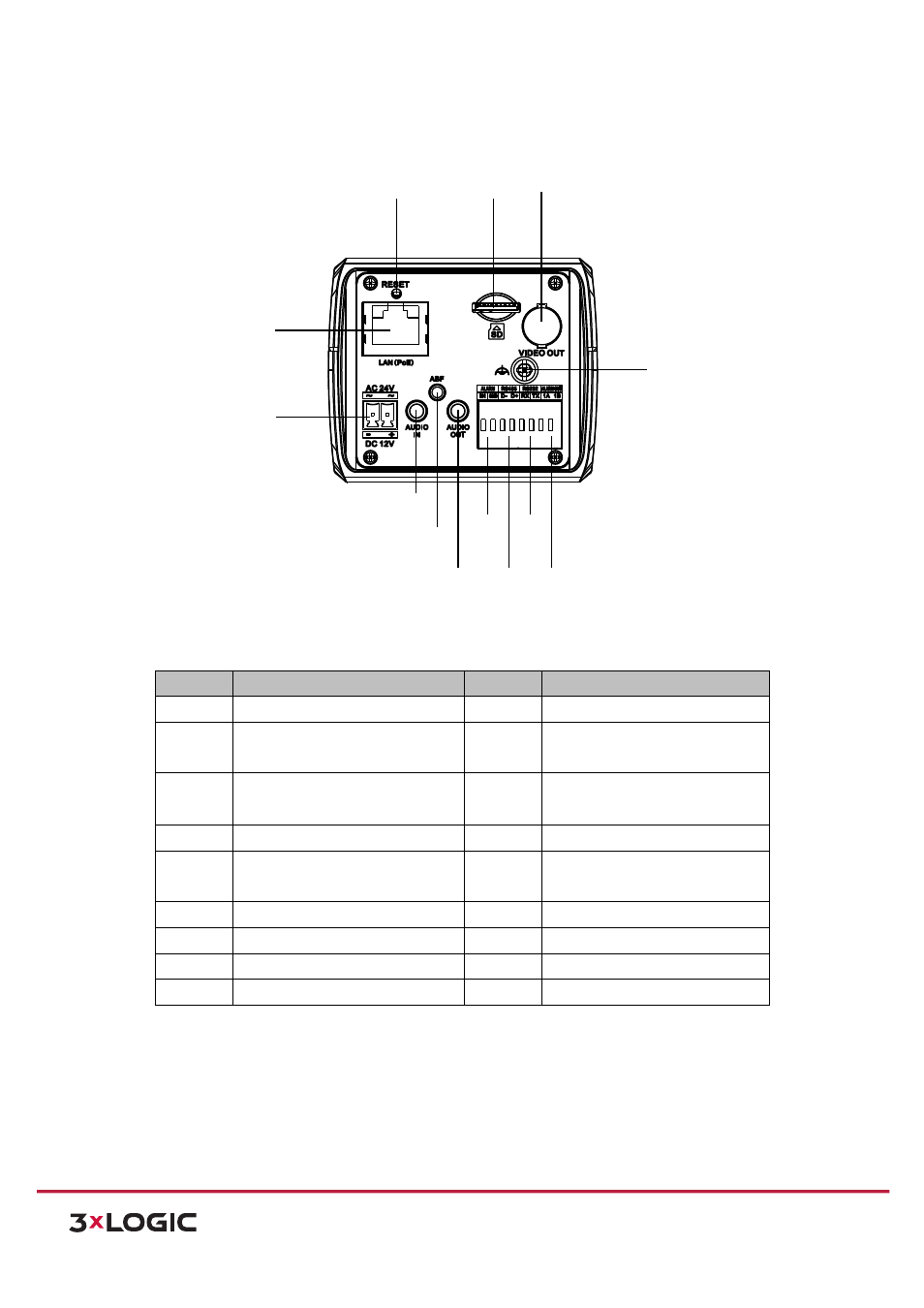
The interfaces on the rear panel are shown below:
Figure 3-‐8
Overview (3)
Description
Table 1-‐3
No.
Description
No.
Description
1
Lens Mount
2
MIC
3
¼-‐20 UNC Screw Hole
4
Status Indicator
5
Auto-‐iris Interface
6
LAN(PoE)
7
Power Outlet
8
Reset
9
Micro SD Card Slot
10
Video Out
11
Grounding
12
1A, 1B: Alarm Out
13
RX, TX: RS-‐232
14
D-‐, D+: RS-‐485
15
IN, GND: Alarm In
16
Audio Out
17
ABF
18
Audio In
NOTE:
Press
and
hold
RESET
for
10s
when
the
camera
is
powering
on
or
rebooting
to
restore
the
default
settings,
including
the
user
name,
password,
IP
address,
port
No.,
etc.
The
auto-‐iris
interface
is
shown
below:
8
6
9 10
7
18
16
11
17
14
13
15
12