Installation manual, Visix network camera – 3xLOGIC VISIX Camera User Manual
Page 22
Installation Manual
|
VISIX Network Camera
10225 Westmoor Drive, Suite 300, Westminster, CO 80021 | www.3xlogic.com | (877) 3XLOGIC
21
4
MIC IN: Audio input interface
5
D+, D-‐: RS-‐485 interface
6
1A, 1B, 2A, 2B: Alarm output interface
7
IN1, GND, IN2, GND: Alarm input interface
8
Power Supply Interface
NOTE:
Hold
RESET
for
10s
when
the
camera
is
powering
on
or
rebooting
to
restore
the
default
settings,
including
the
user
name,
password,
IP
address,
port
No.,
etc.
AVAILABLE MOUNTS
!
D2 Ceiling Flush Mount (3xLOGIC Product #:
VX-‐FM-‐D2
)
!
D2 Wall Mount (3xLOGIC Product #:
VX-‐WM-‐D2
)
!
D2 Wall Mount w/ Junction Box (3xLOGIC Product #:
VX-‐WMJ-‐D2
)
!
Universal Corner Mount (3xLOGIC Product #:
VX-‐CM
)
!
Universal Pole Mount ( 3xLOGIC Product #:
VX-‐POLE
)
INSTALLATION
Ceiling Mounting
Steps:
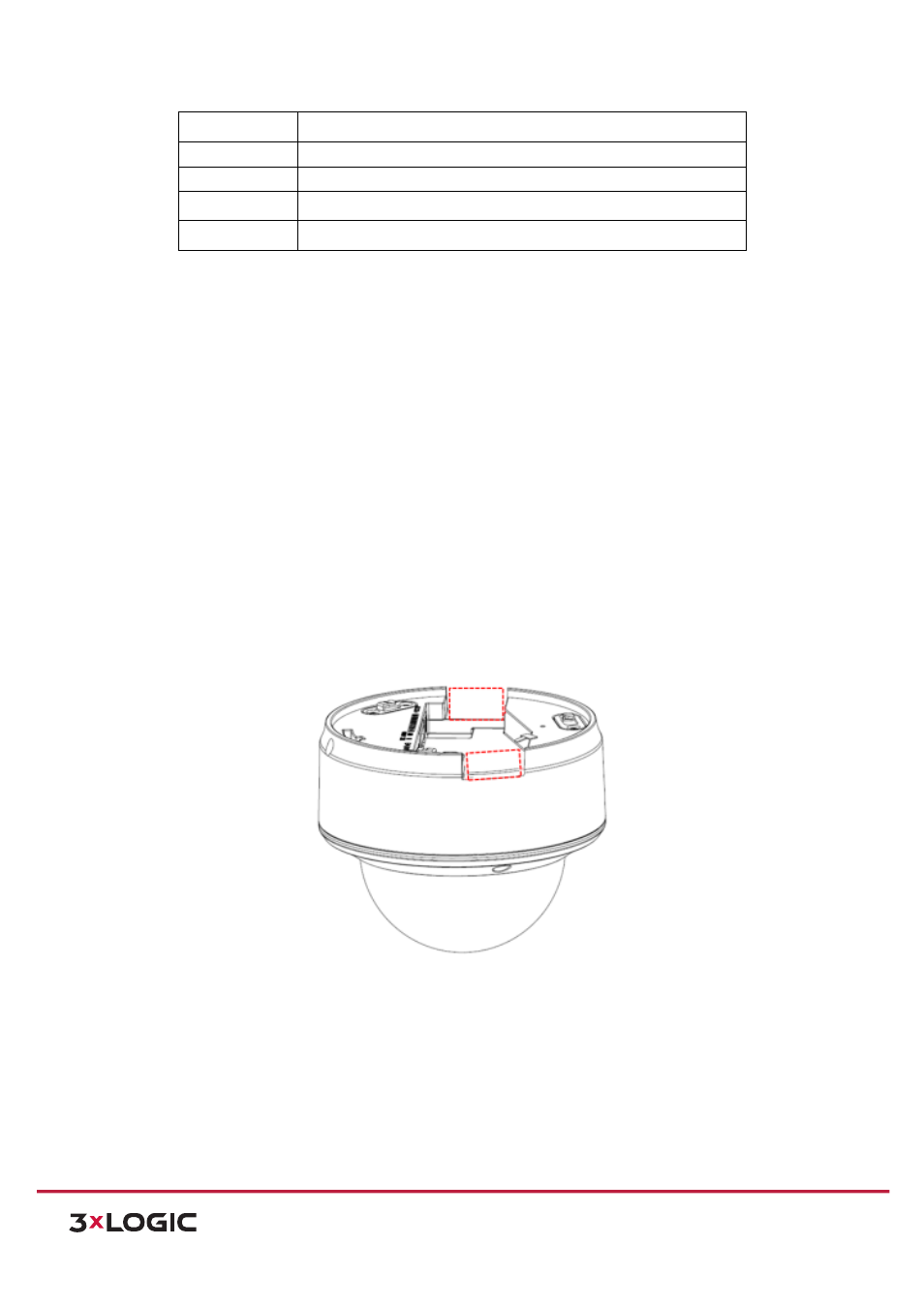
1) (Optional) Use pliers to remove one clip or both clips (marked in dotted line in Figure 4-‐2) on the side of
the back box and then route cables through the opening to secure the cables.
Figure 4-‐2
Side Clips
2) Drill the screw hole and the cable hole according to the supplied drill template.