Switch led indicators, Stacking module led indicators – D-Link DES-3326S User Manual
Page 37
DES-3326S Layer 3 Fast Ethernet Switch User’s Guide
Identifying External Components
37
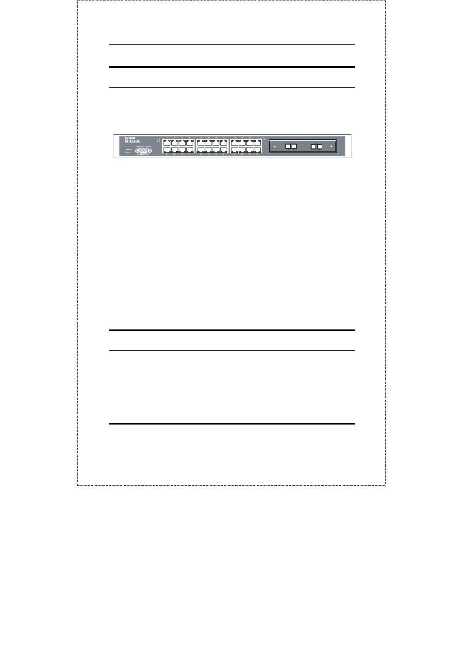
Switch LED Indicators
The LED indicators of the Switch include Power, Console, and
Link/Act. The following shows the LED indicators for the
Switch along with an explanation of each indicator.
Figure 3-12. The LED Indicators
♦ Power This indicator on the front panel should be lit
during the Power-On Self Test (POST). It will light green
approximately 2 seconds after the switch is powered on to
indicate the ready state of the device.
♦ Console This indicator is lit green when the switch is
being managed via out-of-band/local console
management through the RS-232 console port using a
straight-through serial cable.
♦ Act/Link These indicators are located to the left and right of each
port. They are lit when there is a secure connection (or link) to a
device at any of the ports. The LEDs blink whenever there is reception
or transmission (i.e. Activity--Act) of data occurring at a port.
Stacking Module LED Indicators
The switch’s current order in the switch stack is also displayed
on the Stacking Module’s front panel − under the STACK NO.
heading: