Fitting the telescopic chimney stack, Installatie van de telescopi- sche schouw, Installazione camino telescopico – Zanussi NH 100 EAX User Manual
Page 24
Attention! The text in this document has been recognized automatically. To view the original document, you can use the "Original mode".
с
INSTALLATION
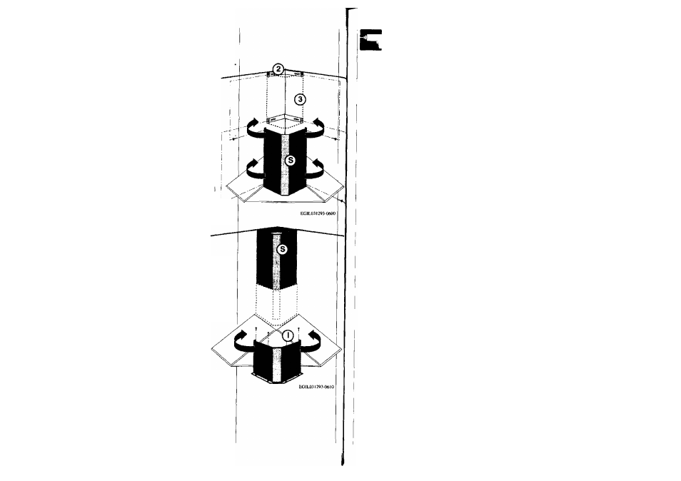
Fitting the telescopic chim
ney stack
• Firstwidenthetwo sides of the
upper section S slightly and in
sert it as shown in the picture.
• Ensure the sides are correctly
fastened on the brackets.
• Secure the upper section to
brackets 3-4 using the screws
provided.
• Position the lower section
I
as
shown in the picture.
* Fix the lower section to the
cooker hood body using the 4
screws provided.
NOTE: The upper S and
lower I sections are fixed to
the brackets through a
spring and the connection
is made by pushing both
sections vigourously to
ward the centre.
C
INSTALLATION
Installation des teleskopier
baren Kamines
• Oberes Teleskopteil S
leicht ausei nanderbiegen
und wie in Abbildung an
bringen.
• Es ist sicherzustellen,
daß die zwei seitlichen
Schenkel gut hinter den
Wandblechen einrasten.
•Oberes Teleskoptei
mittels der beigefügten
Schrauben an die La
schen 3-4 befestigen.
• Unteres Kaminteil
I
wird wie
abgebildet angebracht.
• Unteres Kam inteil wird milden
vier beigefügten Schrauben am
Haubenkörper befestigt.
BEMERKUNG: Die hinteren
Abwickelungen des Teles
kopteiles S und des Kamin
teiles I müssen mit kräfti
gem Druck gegen die Feder
kraft der Wandbleche an
gedrückt werden.
46
INSTALLATION
Installation de la cheminée
téléscopique
• Elargir légèrement la chemi
née supérieure
S
et l’insérer
comme indiqué à la figure.
• Vérifier la prise des pans laté
raux sur les brides.
• Fixer la cheminée supérieure
aux brides 3-4, en utilisant les
vis fournies.
• Positionner la cheminée infé
rieure
I
comme indiqué par la
figure.
• Fixer la cheminée au corps de
la hotte avec 4 vis fournies.
NOTA: L’accrochage des
cheminées S et I en corres
pondance des brides s’ef
fectue par un système de
ressort; pour cela pousser
énergiquement vers le cen
tre.
C
INSTALLATIE
Installatie van de telescopi-
sche schouw
• De bovenste schouwelement
S lichtjes spreiden en hem vol-
gens de tekening invoegen.
• Controleer of de vouwen aan
de zijkant goed aansluiten op
de beugel.
• Bevestig de bovenste buis op
de beugels 3-4 met behulp van
de bijgeleverde schroeven.
• Plaats de onderete buis
I
zo-
als is aangegeven in de afbeei-
ding.
• Bevestig de buis aan de кар
met de vier bijgeleverde schroe
ven.
NB: De bevestiging van de
buizen S en I, corresponde-
rend aan de beugels, moet
worden uitgevoerd door
met kracht naar het midden
te drukken.
47
c
INSTALLAZIONE
Installazione camino telesco
pico
• Divaricare leggermente il ca
mino superiore
S
e inserirlo
come indicato in figura.
• Verificare la corretta presa
delle piegature laterali alle staf
fe.
• Fissare il camino superiore
sulle staffe 3-4,tramite le viti in
dotazione.
• Posizionare il camino inferiore
I
come indicato in figura.
• Fissare il camino al corpo cap
pa con quattro viti in dotazione.
NB: l'aggancio dei camini S
e I in corrispondenza delle
staffe deve essere effettua
to spingendo con energia
verso il centro.