Connector connection diagram – CBM America CBM-262 User Manual
Page 51
6
Chapter 6
Interfaces
42
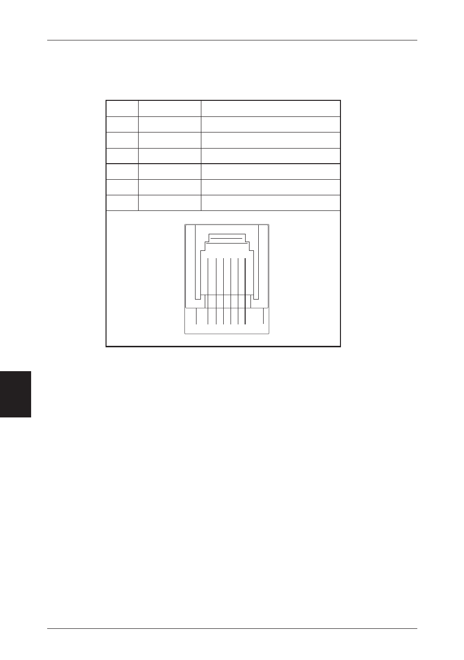
NO.
Signal Name
Function
1
FG
Safety ground.
2
DRAWERI
Drawer 1 drive signal.
3
DRSW
Drawer switch input.
4
VDR
Drawer drive power supply.
5
DRAWER2
Drawer 2 drive signal.
6
GND
Common ground in the circuit.
6
1
Connector Connection Diagram
Connector Used: TM5RJ3-66 (Hirose)
Compatible Connector: Compatible with TM3P-66P (Hirose)
•
No signals are output during printing.
•
Both drawers 1 and 2 cannot be driven simultaneously.
•
Use a 36 ohm or higher drawer solenoid. (Be careful not to let the output current
exceed 0.8A. If the output current exceeds 0.8 A, results cannot be guaranteed.)
•
The drawer kick connector is not the type used for connections to telephone lines. Do
not connect to any device other than a solenoid.