Serial interface, Specifications, Signal lines and pin arrangement – CBM America CBM-262 User Manual
Page 41
6
Chapter 6
Interfaces
32
Serial Interface
Specifications
Transmission Method
Start-Stop Synchronous Full Duplex Communications
Signal Level
RS-232C
Baud Rate
2400, 4800, 9600, 19200
Data Length
7 or 8 bits
Start Bit
1 bit
Stop Bit
Receiving 1 bit; Transmitting 2 bits or more
Parity
Even, Odd, No Parity
Connector
Printer Side Compatible with DDK 17LE-13250-27
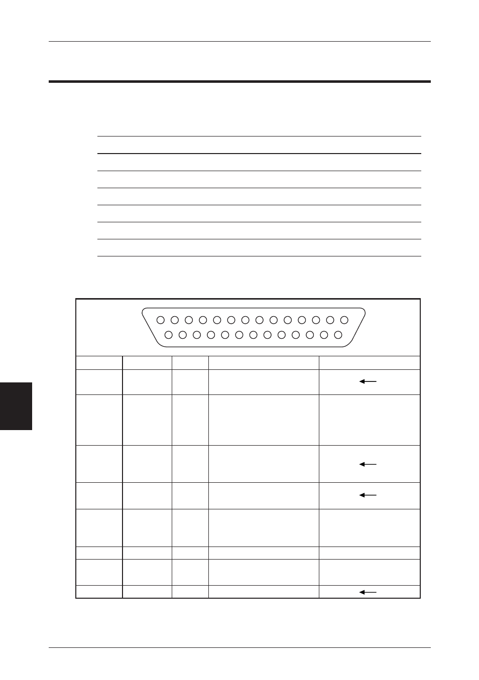
Signal Lines and Pin Arrangement
•
IN indicates a signal from the Host to the printer. OUT indicates a signal from the
printer to the Host.
*1
25pin, INIT is HIGH or the TTL-HIGH level of input (+2V~+15V) .
Pin No.
1
2
3
4
6
7
20
25
Direction
OUT
IN
OUT
IN
OUT
IN(*1)
DTR/DSR
Not used.
Data are sent when the
status information send
signal is “HIGH.”
LOW when Busy.
HIGH when Ready.
13
25
14
1
X-ON/X-OFF
Connects the Host CPU
and printer.
Sends transmission data
and X-ON/X-OFF
signals to the Host CPU
from the printer.
Transmission data from
the Host CPU to the
printer.
Pulls up the signal to
+10V at 3.3k ohms.
Not used.
Always HIGH.
Printer's Reset signal.
Signal Name
F.GND
TXD
RXD
RTS
DSR
S.GND
DTR
INIT