Adjusting the cross trainer e – Sears 831.15934 User Manual
Page 9
Attention! The text in this document has been recognized automatically. To view the original document, you can use the "Original mode".
ADJUSTING THE CROSS TRAINER e
The CROSS TRAINER e is designed to be chonged from stoSon to station quickly and easily. The instructions below
describe how eoch port of the CROSS TRAINER e can be odjusted. Please read these inshuctions carefully before using
the CROSS TRAINER e. Refer to pages 17 through 24 of this owner’s manual to see how the CROSS TRAINER e should
be set up for each individual exercise.
IMPORTANT: For effective exercise, the CROSS TRAINER e must be set up correctly for eoch exercise. When attach
ing the lot bar, rower bar or strap, attoch them directly to the CROSS TRAINER e or use the chain to attcsch them;
make sure that the lot bar, rower bar or strap is in the correct starting position for each exercise. If fher« is any
slack in the cable or chain as you perform an exercise, the effectiveness of the exercise will be reduced.
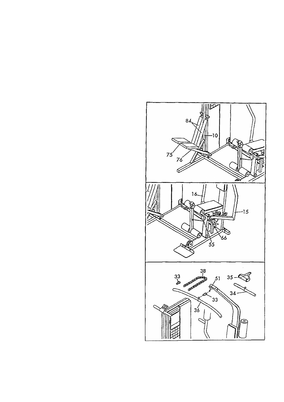
T. CHANGING THE STEPPING RESISTANCE
To change the resistance of the Pedals
[75, 76),
first
lift the Pedals off the hooks at the lower ends of the
Resistance Cylinders {84). Move the hooks to differ
ent slots under the Pedals. Make sure that the hooks
ore fully inserted into the same slots under both
Pedals. The farther the hooks ore from the Tower
Frame (10), the greater the resistance will be,
WARNING: The Resistance Cylinders become very
hot during use. Allow the Resistance Cylinders to
cool before touching them.
2.
CHANGING THE ARMS TO THE BUTTERFLY
MODE AND PRESS MODE
The Arms (15, 16) con be changed to either the but
terfly mode or the press mode. To perform the BUT
TERFLY exercise, change the Arms to the butterfly
mode by turning the Selector Knob (55) so the
Selector Plate (66) is vertical. To perform the BENCH
PRESS exercise, change the Arms to the press mode
by turning the Selector Knob so the Selector Plate is
horizontal.
ATTACHING THE LAT BAR, ROWER BAR OR
STRAP TO THE HIGH PULLEY STATION
Attach the Lot Bar (36) to the Main Coble (51} with a
Cable Clip (33), For some exercises, the Choln (38)
should be ottached between the Lot Bor and the
Main Coble with two Coble Clips. Ad[ust the length
of the Chain between the Lot Bor and the Main
Coble so the Lot Bor is in the correct storting posi
tion for the exercise to be performed.
The Rower Bar (34) or the Strop (35) con be
ottoched in the some manner.
8