Assembly – Sears 831.15934 User Manual
Page 4
Attention! The text in this document has been recognized automatically. To view the original document, you can use the "Original mode".
ASSEMBLY
/vssembly requires two persons. To ossemble tfie CROS3 TRAlNcR e, use tfie included videocosselte or follow (be
instructions below. Due to tfie weight of the CROSS TRAINER e, it should be assembled in the location where it will be
used. Ploce all parts in a cleored area and remove the packing moterials. Do not dispose of the packing moterials until
assembly is completed. Make sure to lower the resistance cylinders and pedals before beginning ossembly; if the
resistance cylinders foil, they may damage the side shields. Read each assembly step and exomine each drawing
carefully. Moke sure that all parts are oriented as shown in the drawings.
The following tools (not included) ore required for ossembly: two 8" Adjustoble Wrenches ___________ and a
Rubber Mallet
i. The included lubrlcont ond a smoil amount of soapy wafer are olso required.
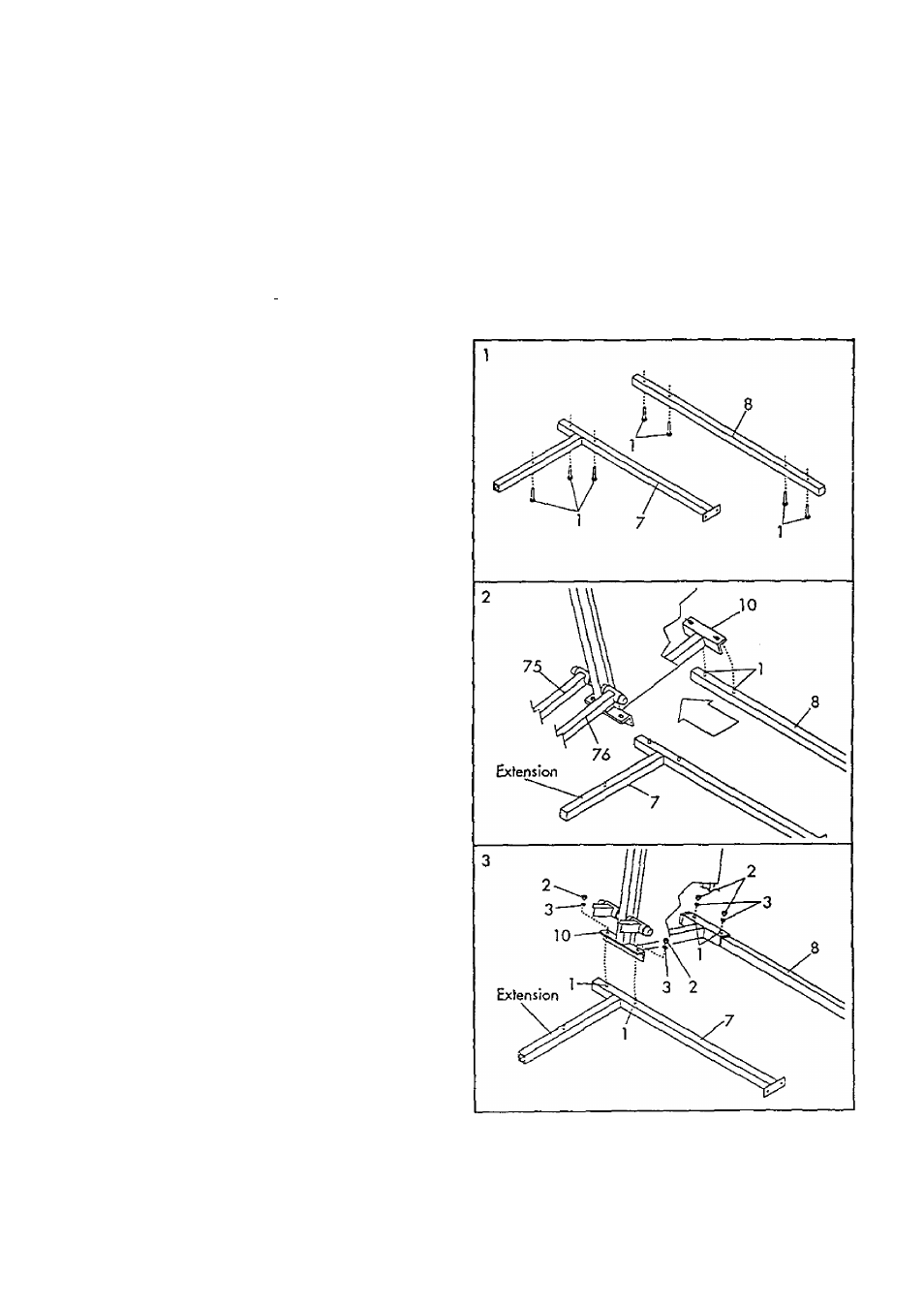
1.
Set the Front Base (7) and the Reor Base (8) on the
floor as shown. Turn the Rear Base so the indented
holes are foword the floor.
Insert seven 3/8' x 2 1/2' Corrioge Bolts (1) up
through the indicated holes in the Front and Rear
Boses (7, 8).
2.
With the help of a second person, set the Tower
Frame (10) neor the indicated ends of the Front ond
Rear Boses (7, 8). The Tower Frame must be turned
so the Pedols (75, 76) are on the some side os the
extension on the Front Bose. Raise the Tower Frame
and lower it onto the two indicoted 3/8' x 2 1 /2'
Carriage Bolts (1) In the Rear Bose.
3.
Raise the front of the Tower Frame (10) ond lower it
onto the two indicated 3/8' x 2 1/2' Corrioge Bolts
(1 ) in the Front Bose (7).
Adjust the position of the Tower Frame (10) so the
four indicoted 3/8' x 2 1/2' Corrioge Bolts (1) ore
centered in the slotted holes in the Tower Frame,
Thread o 3/8' Nut |2) with a-3/8' Loclcwosher (3)
onto each Corrioge Bolt, Do not tighten the Nuts
yet.