Sears 831.15934 User Manual
Page 6
Attention! The text in this document has been recognized automatically. To view the original document, you can use the "Original mode".
7 .
8
.
9.
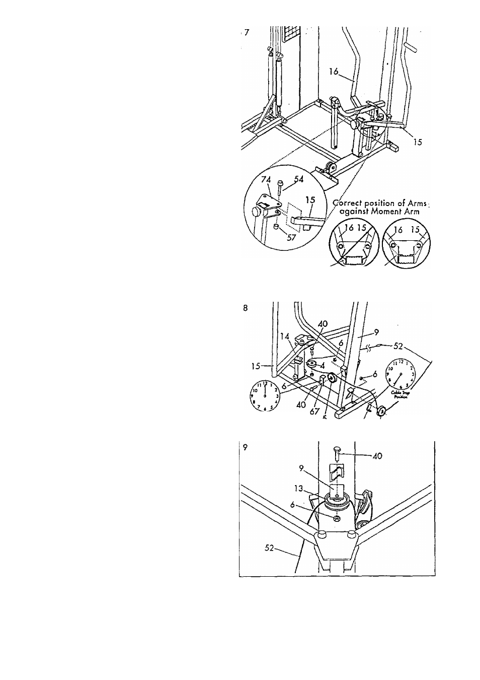
Insert tfie lower end oF the Left Arm (15) into the feft
side of the Moment Aim (74). Make sure that the
bracket on the end of the Left Ann is positioned as
shown in the inset drawing. If the bracket is not
positioned as shown, the Left Arm will not function
properly. '
Align the hole in the end of the Left Arm {15} with
the holes in the Moment Arm
[74].
Insert the 3/4* x
4* Axle (54) into the Moment Arm and the Left Arm.
Top □ 3/4* Plastic Cap (57) onto the Axle.
Attach the Right Arm (16) in the same manner.
Wrap the Weight Coble (52) under a 3 1/2* Pulley
(5). Aftoch the Pulley and a Cable Trap (67) to the
bock of the Upright (9) with a 3/8* x 1 3/4* Bolt
(40) and 3/8' Nylock Nut (6). Ar^ke sure thot the
Cable Trap is in the V o'clock' position.
Lay the Weight Coble (52) over a 3 1/2* Pulley (5).
Attach a Cable Trop (67) and the Pulley to the left
side of the Upright (9) with a 3/8*
X
1 3/4" Bolt
(40) and 3/8* Nylock Nut (6). Moke sure that the
Coble Trop is in the '12 o'clock* position.
Wrap the Weight Coble (52) around
a
2* Pulley (4).
Attach the Pulley to the Left Arm (15) with a 3/8* x
1 3/4* Bolt (40) and 3/8' Nylock Nut (6).
Wrap the Weight Cable (52) oround a 2 3/4*
Pulley (13). Attach the Pulley to the indicated brocket
on the Upright (9) with a 3/8* x 1 3/4* Bolt (40)
ond 3/8* Nylock Nut (6).
74^
^^
74
INCORREa CORREa
Cfihi* Irep
67 c