C2 c3 – TYREDOG TD-2300A-X10 User Manual
Page 21
TD-2300A Series V1.0
19
Installation - Sensors Continued..
Before fitting the sensors to the wheels, it’s important that you know
where each sensor should go.
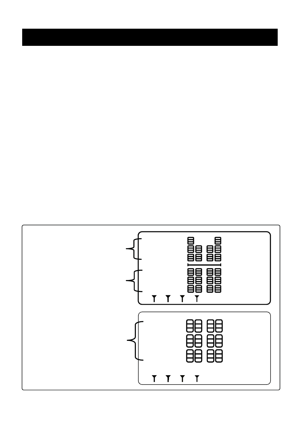
The Diagram below shows the layout and sensor positions for the maxi-
mum 34 Wheel setup.
For all other configuarations, start from the top (Front) and go from left to
right.
Example 4 Wheel: Front Left Wheel (1), Front Right Wheel (2), Rear Left
Wheel (3), Rear Right Wheel (4).
Example 6 Wheel: Front Left Wheel (1), Front Right Wheel (2), Rear Left
Outer Wheel (3), Rear Left Inner Wheel (4), Rear Right Inner Wheel (5),
Rear Right Outer Wheel (6).
PSI
PSI
C
C1
C6
C5
C9 C10
C4
C7 C8
C12
C11
A5 A2
A1 A4
A3
A7
B1
B5
B9
A8
B2
B6
B10
A6
A10
B4
B8
B12
A9
B3
B7
B11
C2
C3
A B
H
A B
T
C
The Truck (A) Unit can
support up to 10 Wheels
The First Trailer (B) can
support up to 12 Wheels
The Second Trailer (C) can
support up to 12 Wheels