Top Flite TOPA0160 User Manual
Page 62
❏
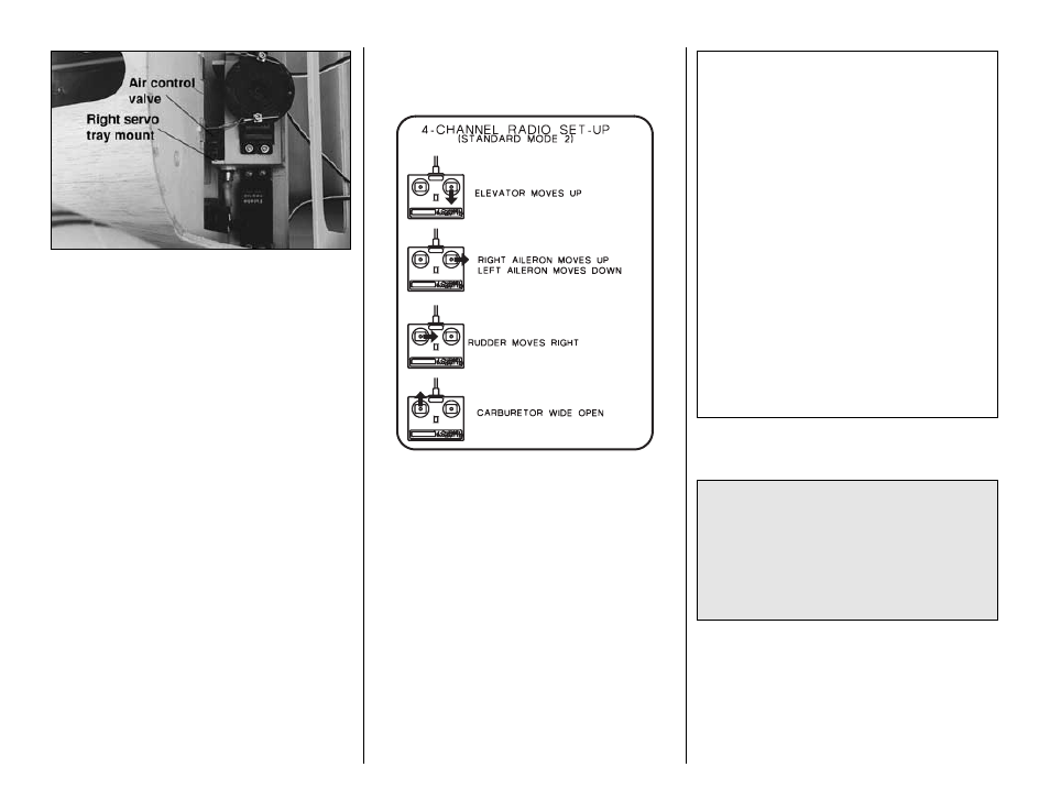
5. Mount your air control valve and servo. On our
prototype we mounted the air control valve to the right
nose steering servo tray. Mount yours the same way or
find an alternate location. Mount the servo to two rails
made from leftover 1/4” x 3/8” [6.4 x 9.6mm] basswood.
Note: It will be easier to connect your air lines to the
air control valve before you mount the air control
valve in the airplane.
❏
6. Mount your on/off switch and charge jack in a
location where it will not get covered with engine
exhaust residue. We used the Great Planes
Mounting Set (GPMM1000).
❏
7. Connect your battery pack, receiver, switch and
servos. Connect the air lines to your air tank with a
“T” fitting connected to your air fill valve. If you are
installing the Cabin Interior, route the air lines and
servo cords through notches in the formers.
❏
8. Recheck the C.G.
❏
9. If you haven’t already centered your servos, take
the servo arms off all the servos and turn on your
transmitter and receiver (this is most important for the
flaps). Center the trims and put the servo arms back on
your servos and secure them with the screw.
❏
10. While you’re at it, double-check all the servos
and make sure the servo arms are secured and all
the clevises have a silicone retainers.
❏
11. Make sure the control surfaces move in the
proper direction as illustrated in the following sketches.
❏
12. Adjust your pushrod hookups and set up your
radio to provide the control surface movements
as follows.
The surface throws and balance point listed in this
manual are the ones at which the T-34B flies best.
Set up your aircraft to those specifications. If, after
a few flights, you would like to adjust the throws to
suit your tastes, that is fine. The T-34B has large
elevators and does not require much throw. Too
much throw can force it into a stall, so
remember...More is not better.
CONTROL SURFACE THROWS:
We recommend the following control surface
throws:
Note: Throws are measured at the widest part of
the control surface.
High Rate
Low Rate
ELEVATOR:
11/16” up
9/16” up
11/16” down
9/16” down
RUDDER:
1” right
3/4” right
1” left
3/4” left
AILERONS:
3/4” up
1/2” up
3/4” down
1/2” down
FLAPS:
Takeoff
Landing
1” down 2” down
(50%)
(100%)
-62-