Top Flite TOPA0160 User Manual
Page 39
❏
9. Insert the rudder torque rod into the hole in the
stab from the bottom. Use a heavy duty pair of pliers
to make the 90 degree bend in the torque rod. This
bend is not hard to make if you hold the vertical
portion of the torque rod with the pliers and then use
your thumb, or another pair of pliers, to bend the
torque rod over. Midway through the bend check that
it is 90 degrees to the threaded end of the rod.
❏
10. Make a 1/2” x 1/2” [12.7 x 12.7mm] bearing block
from some leftover 1/8” [3.2mm] ply. Drill a 1/8” [3.2mm]
hole in the center of the block and install it on the torque
rod on the bottom of the stab. Glue it in place with
medium CA, being careful not to get any on the torque
rod. Make sure that the nylon swivel horn has been
installed on the threaded end of the torque rod, with the
tab pointing towards the front of the stab.
❏
11. Cut 7” [177.8mm] from the non-threaded end
of a .074” x 36” [1.9 x 916mm] pushrod wire. Clean
residual oil from the wire with a cloth dampened with
alcohol or other solvent. Cut six 1/4” [6.4mm] long
bushings from the white inner pushrod tube, then
slide the bushings evenly spaced onto the wire.
Make sure the bushings at the ends of the wire will
not protrude from the guide tube or the control could
become stuck during flight. If the bushings slide onto
the wire easily, hold them in place with a drop of thin
CA. Make sure the CA cures before you proceed so
you do not inadvertently glue the pushrods into the
guide tubes! Slide a silicone retainer onto a nylon
clevis and thread the clevis onto the wire about 15
full turns. Make a second pushrod the same way.
❏
12. Cut the rudder pushrod tube, on the left side
of the fuselage, so that it extends only 2” [51mm] aft
of former F10. Connect one of the pushrods to the
nylon swivel horn on the rudder torque rod and slide
the silicone retainer into place. Slide the pushrod into
the rudder pushrod tube in the left side of the
fuselage. Slide the other pushrod into the elevator
pushrod tube. Position the stab on the stab saddle.
Place a weight on top of the stab to hold it in place.
CENTER THE STAB
❏
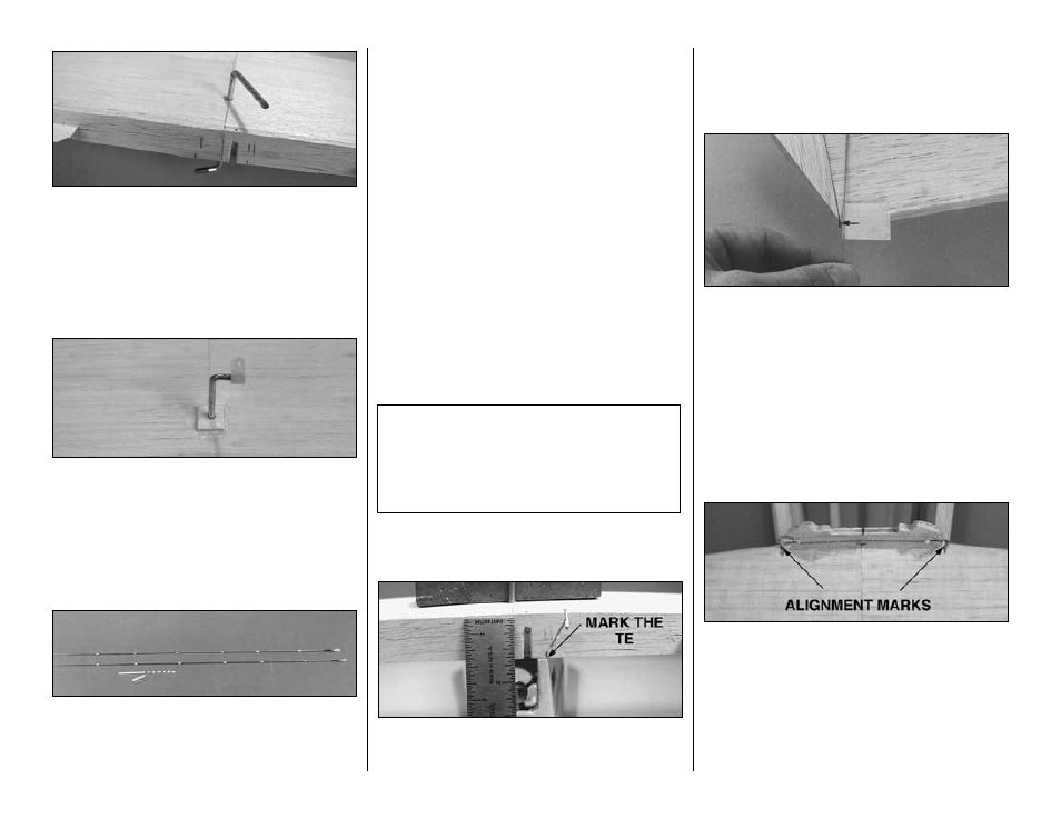
1. Align the TE of the stab with the center of former
F11. Mark the TE of the stab above the stab saddles.
Pin the stab TE to the stab saddle in this position.
❏
2. Insert a T-pin in the center of the top of
the firewall.
❏
3. Tie a loop on one end of a 54” [1372mm] piece
of string and connect it to the T-pin in the top of the
firewall. Put a piece of masking tape with an arrow on
it near the other end of the string. Slide the tape
along the string and align the arrow with the corner
of one of the stab halves. Swing the tape over to the
other corner on the other side of the stab. Shift the
stab and slide the tape along the string until the
arrow aligns with both corners of the stab.
❏
4. Mark the LE of the stab where it aligns with
former F10A.
Beech Quote: “The Beechcraft Bonanza is a
masterpiece of engineering; it’s an airplane that
constitutes a modern miracle of aeronautical
design; and in our opinion, marks a new milestone
in the progress of aviation.” —Walter H. Beech,
August 1, 1946
-39-