Top Flite TOPA0160 User Manual
Page 46
❏
11. Mark the engine mounting bolt holes on the
mount. Hint: Mark the holes with a wire rod
sharpened at one end. Heat the tip of the rod with a
torch to dimple the engine mount in the center of the
holes. The Great Planes Dead Center Tool
(GPMR8130) also works well.
❏
12. Remove the engine from the mount and the
mount from the firewall. Use a drill press, if you have
access to one, or use a hand drill to drill the holes
with a #29 or 9/64” drill bit for 8-32 screws. Tap 8-32
threads into the mount. Screw the mount back onto
the firewall. Screw the engine to the mount with 8-32
x 1” socket head cap screws, #8 lock washers and #8
flat washers to see how it fits.
MOUNT THE NOSE LANDING GEAR
Continue with these instructions if you are installing
fixed landing gear. If you are installing retracts, skip
to
Retractable gear on page 47.
Fixed gear
❏
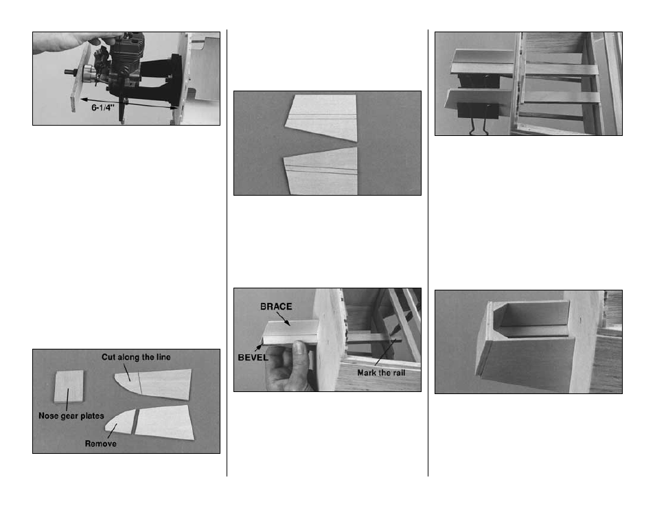
F1. Draw a line connecting the punch marks on
both die-cut 1/8” [3.2mm] plywood nose landing
gear braces. Cut the braces off at the line. Glue the
two die-cut 1/8” [3.2mm] plywood nose gear plates
together. Make sure the punch marks face out.
❏
F2. Place the braces over the nose gear detail on
the plan. Mark the location of the 1/4” [6.4mm]
plywood landing gear rails onto the braces.
❏
F3. Remove the engine mount from the firewall.
❏
F4. Cut a bevel on the end of the 1/4” x 9/16” x 9” [6.4
x 14.3 x 228.6mm] plywood landing gear rails to
match the angle on the end of the braces. Test fit a rail
through the right side of the firewall and in the notch in
former F2. Position the right brace and align the front of
the rail with the front of the brace. Mark the rail 1/8”
[3.2mm] aft of former F2. Remove the rail and cut it at
the mark. Mark the other rail in the same manner.
❏
F5. Use 30-minute epoxy to simultaneously glue
the rails to the firewall and former F2, and the rail
braces to the rails and the firewall. Make sure the
front of the rails are even with the front of the braces.
❏
F6. Drill 1/8” [3.2mm] holes through the punch
marks in the nose gear plate. Press four 4-40 blind
nuts into the holes in the plate, and secure them with
thin CA.
❏
F7. Position the nose gear plate on the front of the
braces. Trim the rails so the blind nuts do not
interfere. Use 30-minute epoxy to glue the nose gear
plate to the rails and rail braces. Hold the plate in
position with masking tape until the epoxy is fully
cured. Add balsa triangle braces as shown on the
plan cut from leftover fuse corner stringers. See the
photo below at step 8.
-46-